|
Thread Number: 11383
Bendix Spin problem... |
[Down to Last] |
Post# 204240 4/15/2007 at 19:27 (6,214 days old) by pulsator  (Saint Joseph, MI) (Saint Joseph, MI) |
||
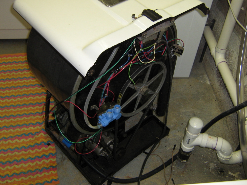
A while back, Austin was kind enough to send me his Bendix Deluxe washer. I've finally today gotten around to rewiring the whole machine, I have yet to test the new inlet valves, but, first things first. The machine won't spin, it'll tumble and drain just fine, but it just doesn't wanna kick into spin! The solenoid doesn't seem to have any current running through it. I ran all the new wires very carefully and replaced one wire at a time with a new one until all had been replaced. I just don't know... Could the solenoid be bad? Could it be the timer? I dunno what to do now. Here's a pic of the new wiring:
| ||

|
|
Post# 204289 , Reply# 2 4/15/2007 at 21:36 (6,214 days old) by jetcone (Schenectady-Home of Calrods,Monitor Tops,Toroid Transformers) |
||
Jamie | ||
|
Post# 204292 , Reply# 3 4/15/2007 at 21:37 (6,214 days old) by unimatic1140 (Minneapolis) |
||
 | ||
|
Post# 204293 , Reply# 4 4/15/2007 at 21:41 (6,214 days old) by pulsator (Saint Joseph, MI) |
||
|
| ||
|
Post# 204300 , Reply# 5 4/15/2007 at 21:52 (6,214 days old) by unimatic1140 (Minneapolis) |
||
|
OK so then the next test will be to build a test cord to manually test the solenoid. What you will need to do is to go to your local hardware store and get a replacement cord and some bullet connectors. Jamie do you have or does you Dad have a wire crimp tool? I assume you do since you just rewired the washer. What you do is strip off the end of the each wire of the new cord (one white, one black) and attach the bullet connectors using the crimp tool. Then you remove the two wires from the solenoid and attach the bullet connectors into each of the two connections of the solenoid and plug the cord into the wall socket. If the solenoid snaps on you know the problem is elsewhere.
| ||
|
Post# 204307 , Reply# 6 4/15/2007 at 22:00 (6,214 days old) by pulsator (Saint Joseph, MI) |
||
|
| ||
|
Post# 204308 , Reply# 7 4/15/2007 at 22:02 (6,214 days old) by unimatic1140 (Minneapolis) |
||
|
| ||
|
Post# 204309 , Reply# 8 4/15/2007 at 22:03 (6,214 days old) by pulsator (Saint Joseph, MI) |
||
|
| ||
|
Post# 204310 , Reply# 9 4/15/2007 at 22:07 (6,214 days old) by unimatic1140 (Minneapolis) |
||
|
You need to test the two wires that go into the spin solenoid. Place one wire in each of the aligator clips of the Multimeter. BE SURE TO SET THE DIAL OF THE TESTER TO AC/120 VOLTS otherwise you will ruin the Mutlimeter. Make sure that the wires are secure and do not teach each other or anything else for that matter. Plug the washer into your power strip and with the power strip turned off set the timer dial to spin. Flip the power on and does the Multimeter read 110 to 125 volts? | ||
|
Post# 204312 , Reply# 10 4/15/2007 at 22:10 (6,214 days old) by pulsator (Saint Joseph, MI) |
||
|
| ||
|
Post# 204316 , Reply# 11 4/15/2007 at 22:26 (6,214 days old) by jetcone (Schenectady-Home of Calrods,Monitor Tops,Toroid Transformers) |
||
|
Jaimie | ||
|
Post# 204317 , Reply# 12 4/15/2007 at 22:26 (6,214 days old) by jetcone (Schenectady-Home of Calrods,Monitor Tops,Toroid Transformers) |
||
|
2 | ||
|
Post# 204318 , Reply# 13 4/15/2007 at 22:27 (6,214 days old) by jetcone (Schenectady-Home of Calrods,Monitor Tops,Toroid Transformers) |
||
|
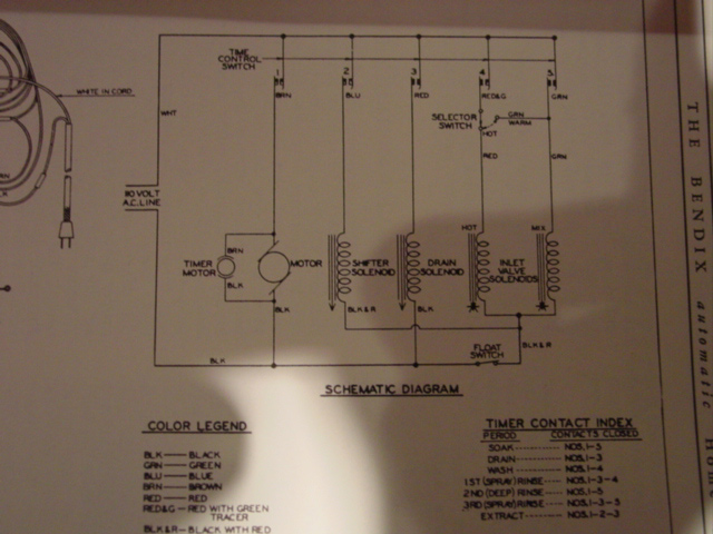
Diag 3 Schematic | ||
|
Post# 204319 , Reply# 14 4/15/2007 at 22:34 (6,214 days old) by jetcone (Schenectady-Home of Calrods,Monitor Tops,Toroid Transformers) |
||
|
looking at the last one
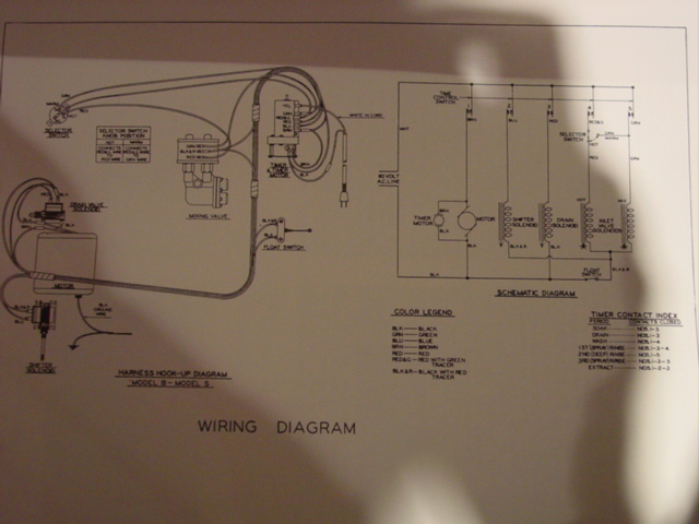
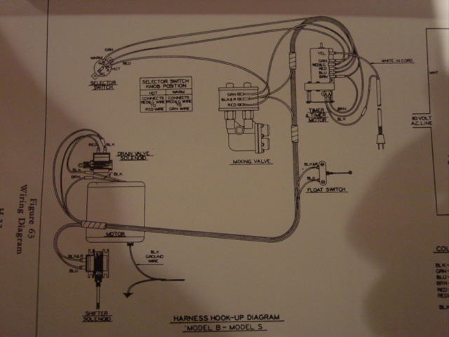
You'll see that the BLUE wire should run from the timer block to the spin (shifter) solenoid,then a black wire should run from the spin solenoid to the BOTTOM of the water valve as the neutral wire for both the valves and the solenoid. Check to see if the black wire got hooked to the top of one of the valves instead of being on the bottom and common to both valves. The hot solenoid should have a red running down from the selector switch and there should be a GREEN-RED running from that switch up to the timer block. Then there should be a GREEN wire running from the GREEN contact on the timer block. Check to see you have that HOT-WARM switch in the circuit see on the diagram where it says SELECTOR SWITCH. DO this with NO POWER to the machine , uplugged. | ||
|
Post# 204322 , Reply# 15 4/15/2007 at 22:39 (6,214 days old) by unimatic1140 (Minneapolis) |
||
|
Yes I see Jon and I are doing the same thing at the same time! LOL. Look at this wiring diagram, there is a blue wire going from the timer (contact #2 or BLU) to the one terminal of the spin solenoid. Now the other wire goes from the other terminal of the spin solenoid into the WATER LEVEL SWITCH. This tells us that if the water level switch is stuck in the up (or tub full of water) position it will not allow the machine to spin. By chance is the water float stuck in the up position???? 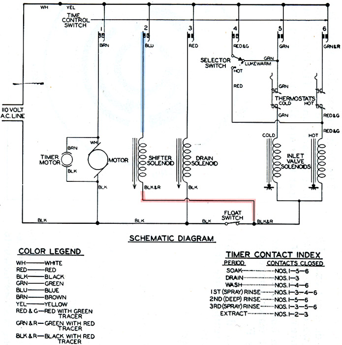
| ||
|
Post# 204324 , Reply# 16 4/15/2007 at 23:11 (6,214 days old) by pulsator (Saint Joseph, MI) |
||
|
| ||
|
Post# 204333 , Reply# 17 4/15/2007 at 23:38 (6,214 days old) by pulsator (Saint Joseph, MI) |
||
|
| ||
|
Post# 204388 , Reply# 18 4/16/2007 at 09:26 (6,213 days old) by unimatic1140 (Minneapolis) |
||
|
Jamie there should be a wire that goes from the Water Level Switch (BLACK-Red Tracer) to both the water valve and the spin solenoid. How do you know the switch from the water level float is working? Just because the float goes up and down doesn't mean that the switch is working properly. To test it for sure you need to tie both points of the water level switch together and see if it spins. | ||
|
Post# 204443 , Reply# 19 4/16/2007 at 14:02 (6,213 days old) by pulsator (Saint Joseph, MI) |
||
|
| ||
|
Post# 204447 , Reply# 20 4/16/2007 at 14:11 (6,213 days old) by unimatic1140 (Minneapolis) |
||
|
| ||
|
Post# 204873 , Reply# 21 4/17/2007 at 21:32 (6,212 days old) by jeff_adelphi (Adelphi, Maryland, USA) |
||
I think the problem may be due to the change from a three wire inlet valve to a four wire valve. The wire that comes from the spin solinoid to the water valve, shown in red on the diagram, must connect to one terminal of the cold valve solinoid and, one terminal of the hot valve solinoid and, then go on to connect with one terminal of the float switch. In other words you should have one wire with four terminals to connect all four of these points together. I hope this helps, Jeff
| ||
| Forum Index: | 
| Other Forums: |

|

|

|

|

|

 Comes to the Rescue!