|
Thread Number: 40622
My Electronics Project (Proper One) |
[Down to Last] |

|
| Post# 602344 , Reply# 4 6/10/2012 at 11:33 (4,337 days old) by hotpointfan (United Kingdom) | ||
Possibility | ||
| Post# 602346 , Reply# 5 6/10/2012 at 11:41 (4,337 days old) by hotpointfan (United Kingdom) | ||
|
Confirmed | ||
| Post# 602656 , Reply# 6 6/11/2012 at 13:21 (4,336 days old) by henrypeter21 () | ||
|
Design ... 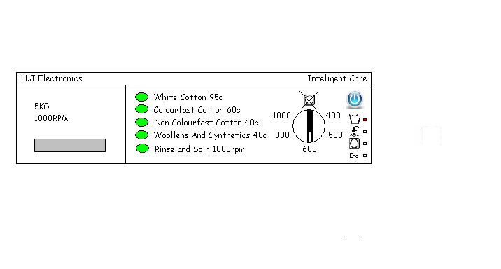
| ||
| Forum Index: | 
| Other Forums: |

|

|

|

|

|

 Comes to the Rescue!


