|
Thread Number: 43694
Repair of a Panasonic Inverter Microwave |
[Down to Last] |
Post# 641950 11/27/2012 at 01:36 (4,167 days old) by kb0nes  (Burnsville, MN) (Burnsville, MN) |
||
My girlfriends parents 10 year old Panasonic microwave quit working a while back. It emitted a noxious cloud of smoke and no longer continued to heat. While this isn't a classic microwave in any way, it is still much better built then the typical low cost junk of today. I figured I'd at least take a peek under the hood before junking it.
For the record it is a NN-T990 Inverter design from about 2000. 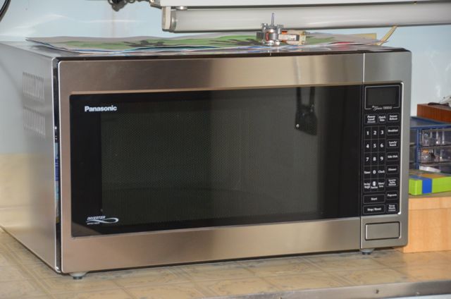
| ||

|
|
Post# 641951 , Reply# 1 11/27/2012 at 01:39 (4,167 days old) by kb0nes (Burnsville, MN) |
||
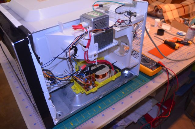
|
Under the hood | ||
|
Post# 641952 , Reply# 2 11/27/2012 at 01:49 (4,167 days old) by kb0nes (Burnsville, MN) |
||
|
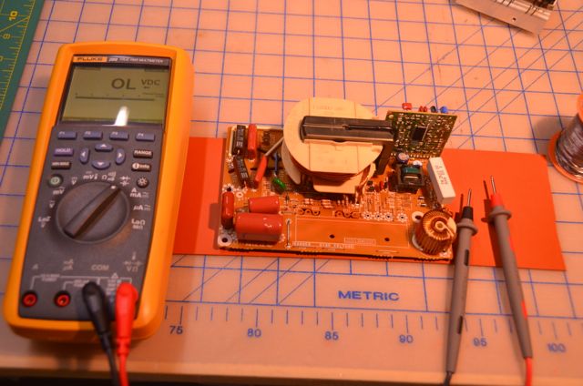
Inverter board
This is the inverter printed circuit board. It takes in 120v mains AC, rectifies it into DC, then chops that at ~36Khz into the large transformer in the center of the board. The two square diodes on the right side rectify the high frequency AC and voltage double it. HV output is ~4000v DC at 300ma! There is also a smaller filament coil to supply current to the magnetron filament.
The heatsink in the back cools the line voltage diode bridge, and two IGBT (Insulated Gate Bipolar Transistors) In the lower left standing vertically is the control and monitoring sub PCB. The white connector in front of that supplies a variable pulse signal from the front panel control board to vary inverter output power and therefore reducing RF cook power. The small black IC's are optical isolators that save the front control board if the Inverter destroys itself! As a word of warning, 4 kilovolts at 300ma is scary power! This can and will kill you dead if you get it wrong. Panasonic officially suggests against ANY repair of the inverter board. Don't do what I did!! ;) 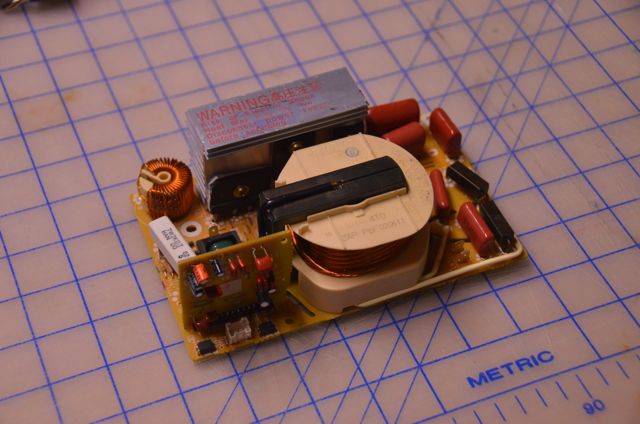
| ||
|
Post# 641953 , Reply# 3 11/27/2012 at 01:53 (4,167 days old) by kb0nes (Burnsville, MN) |
||
|
Well here is your problem...
Not a lot of trouble shooting skill needed here!
The smaller IGBT has totally blown off a leg and all the magic smoke has escaped from the package. This may have something to do with the reduced power! For the record the smaller transistor is the one in series with the transformer primary that chops the input current. The larger one in the middle is some form of a "freewheeling" control that is actually across the primary of the transformer. Later inverter models have since lost this transistor. 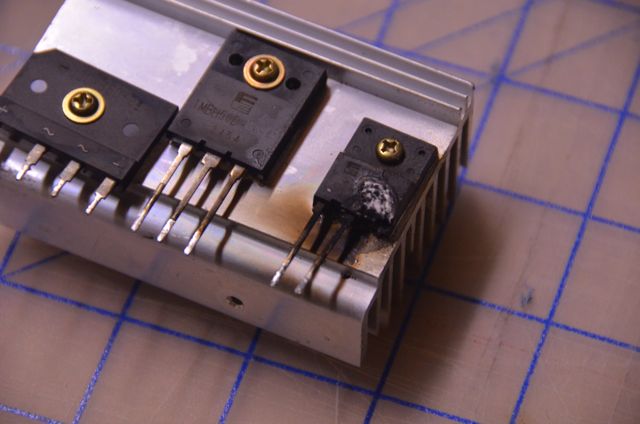
| ||
|
Post# 641954 , Reply# 4 11/27/2012 at 01:57 (4,166 days old) by kb0nes (Burnsville, MN) |
||
|
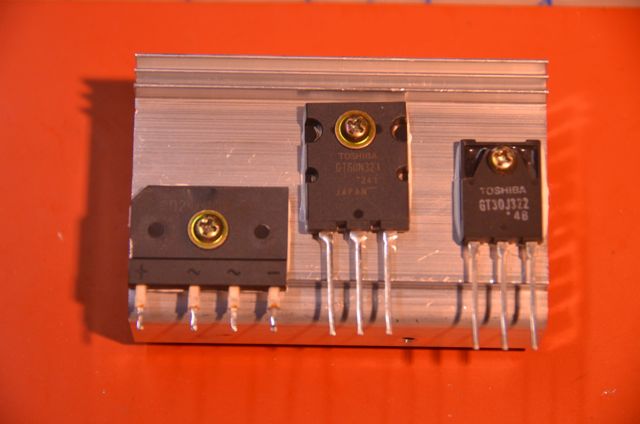
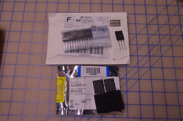
New Parts
Panasonic initially had a kit out that replaced both the IGBT transistors with different, higher rated devices. Apparently they had problems with blowups on the early model inverters. I had to do a bit of searching but I was able to locate both these vintage components. The smaller one I was only able to find from an Ebay seller in Hong Kong. They were very inexpensive but they were shipped on the slow-boat-from-China! The larger IGBT was available from Mouser.
| ||
|
Post# 641955 , Reply# 5 11/27/2012 at 01:59 (4,166 days old) by kb0nes (Burnsville, MN) |
||
|
Heatsink Assembly | ||
|
Post# 641956 , Reply# 6 11/27/2012 at 02:03 (4,166 days old) by kb0nes (Burnsville, MN) |
||
|
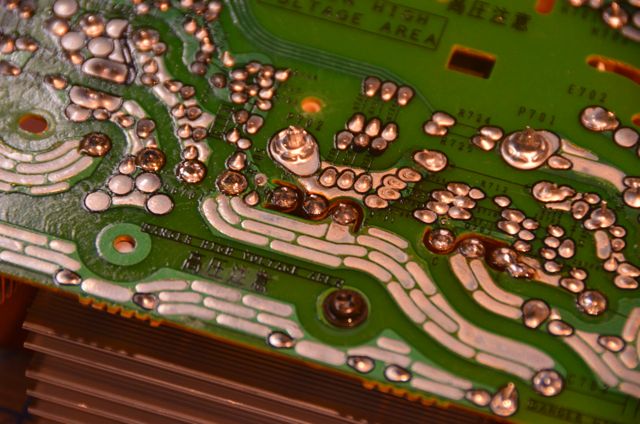
Checking over the rest of the board
I went over the rest of the board both visually and checking what I could with a diode tester. There were a couple smaller diodes that had vaporized from the fault. Also I noticed one of the film capacitors had a crack in its cover. Not likely a problem but I swapped it out too. I got a donor inverter board from a friend who works at a local repair shop I was able to salvage some parts from.
| ||
|
Post# 641957 , Reply# 7 11/27/2012 at 02:09 (4,166 days old) by kb0nes (Burnsville, MN) |
||
|
New transistors soldered into place | ||
|
Post# 641958 , Reply# 8 11/27/2012 at 02:12 (4,166 days old) by kb0nes (Burnsville, MN) |
||
|
Fan cleaned and oiled
Testing the fan here. One concern was cooling. Panasonic's latest inverter models have a different inverter design and a larger fan/improved shroud for better cooling. The "factory" fix for this model now is a "kit" that substitutes out the inverter and fan for the new and improved models.
I figured the least I could do was to clean and oil the open frame motor. 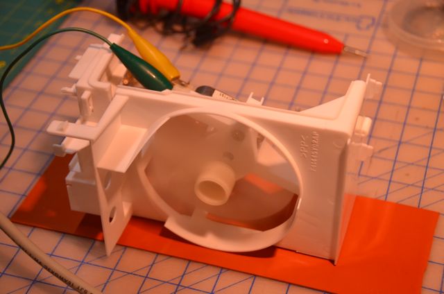
| ||
|
Post# 641959 , Reply# 9 11/27/2012 at 02:17 (4,166 days old) by kb0nes (Burnsville, MN) |
||
|
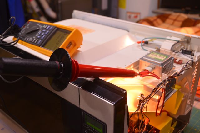
Cross everything you have!
With fingers and toes (and everything else I could cross) crossed, I turned it on and hoped it would work. These high voltage solid state supplies can be feeble and fickle. Amazingly there was no plume of smoke nor was the room plunged into darkness! After 30 seconds the water in the cup I had inside the cavity for a load was noticeably warmer!! Success! Here is a shot of the setup to test the HV
| ||
|
Post# 641960 , Reply# 10 11/27/2012 at 02:23 (4,166 days old) by kb0nes (Burnsville, MN) |
||
|
That should do it!
Meter shows 3.6Kv DC into the magnetron.
I buttoned it up then gave it some run time. Its looks as if the case forms part of the fan ducting so I would be careful about running one of these for too long with the case off. I brought water to a boil several times and at this point I claim a successful repair. Another appliance saved from the landfill! Hopefully there will be some interest in this story. Again I will reiterate that a repair like this isn't for the uninitiated. Lethal voltages like these demand great respect. Only because I have experience with high voltage supplies from tube transmitters did I feel confident tackling this. Be safe and beware! Phil 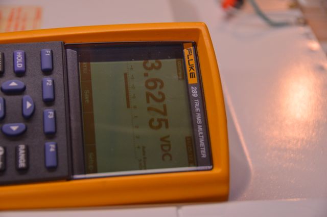
| ||
|
Post# 642017 , Reply# 12 11/27/2012 at 09:29 (4,166 days old) by kb0nes (Burnsville, MN) |
||
|
Rex,
Indeed there are a number of experimenters that are using these boards as part of a HV plate supply for transmitters, amplifiers or just Tesla coils to see how big a spark they can make. I got a lot of useful information from a ham in Australia who reverse engineered the unit to make a 2000 volt 1Kw plate supply for a tube RF amp. Panasonic of course provides no technical information since the unit is "non-repairable". What kind of broadcast gear do you work on? Radio/TV, AM/FM?? That game has sure changed in the past 15 years. From big air cooled tubes with handles on them to a bunch of combined smaller solid state amps. Its amazing what some of the RF transistors can do today (MRF151G comes to mind). I used to believe that anything over 100w needs a filament, but I am changing my luddite ways now. 73 Phil, KB0NES | ||
| Post# 642019 , Reply# 13 11/27/2012 at 09:31 (4,166 days old) by marthalover4eve () | ||
|
safer would it not be safer to get rid of it | ||
| Post# 642024 , Reply# 14 11/27/2012 at 09:43 (4,166 days old) by westingman123 () | ||
|
fascinating! I must admit, a lot of it was over my head. Even so, I learned some things and am most impressed with the repair. That's a handsome appliance, glad you could save it. | ||
|
Post# 642026 , Reply# 15 11/27/2012 at 10:01 (4,166 days old) by kb0nes (Burnsville, MN) |
||
|
Safer??
Get rid or what, the entire Microwave? Might be safer yet to just disconnect the AC mains from the house! ;)
I don't consider anything I did to be unsafe, I took more risks driving to work today. Many of the things in life we do are aren't safe, but what would life be like if we avoided it all? Its all about knowing the risks each of us can manage in a reasonable manner. | ||
|
Post# 642042 , Reply# 17 11/27/2012 at 10:50 (4,166 days old) by super32 (Blackstone Massachusetts) |
||
interesting | ||
|
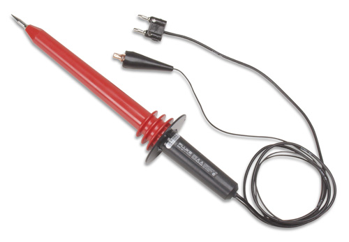
Post# 642111 , Reply# 19 11/27/2012 at 15:21 (4,166 days old) by kb0nes (Burnsville, MN) |
||
|
HV Probe
Phil, I agree the HV probe is a handy addition to any normal DMM. Its just a super insulated probe with a large resistive voltage divider in it. It simply reduces the AC or DC voltage by 1000 times to therefore read 3.6Kv as 3.6 volts. You could use the probe with any 10Meg Ohm input DMM. The one I have is a 40Kx Fluke model but there are a number of other makers that sell them for far less, I got a great deal on the one I have on Ebay.
| ||
| Post# 642211 , Reply# 22 11/28/2012 at 01:04 (4,166 days old) by arbilab (Ft Worth TX (Ridglea)) | ||

Nice photostory b0nes. Illustrates that appliances can be repaired at component level rather than module.
Inverter u'wave is very clever. Much lighter, cook better, more conservative of resources. Instead of alternating max/off, proportion continuous power. Last thing that shocked me was 400V 650W 100kHz inverter. Working on these, use extreme caution and wear eye protection. When those FETs explode they throw shrapnel. | ||
| Post# 642345 , Reply# 23 11/28/2012 at 16:03 (4,165 days old) by PhilR (Quebec Canada) | ||
 That's a very interesting thread Phil. Thanks for showing us! I have friends who have an over-the-range version of this Panasonic inverter and they had problems with it just two years after they got it... I think they paid almost $200 to have it repaired, which is a lot more than the price of a new cheap counter-top microwave. | ||
|
Post# 642552 , Reply# 25 11/29/2012 at 09:15 (4,164 days old) by gansky1 (Omaha, The Home of the TV Dinner!) |
||

Very interesting! I also have a Panasonic Inverter microwave - our daily driver in the kitchen and it's performed great in the five years we've had it. We have the smaller version with the dial control. For $100 at Costco, it's been the best microwave I've ever used. If it quits working, I'd likely shed a crocodile tear, have to toss it and look for another Inverter model.
Would never attempt a repair like this unaccompanied by a trainer , I'd surely be dead! Thanks for the introductory course and responsible safety warnings. Fascinating. | ||
|
Post# 642750 , Reply# 26 11/30/2012 at 00:40 (4,164 days old) by kb0nes (Burnsville, MN) |
||
|
Inverter Microwaves
Just like other switching power supplies the high voltage inverter power supplies were feeble at first. Even more so because faults at HV cause catastrophic failures to solid state electronics instantly.
They have finally started to become highly reliable and they offer advantages of cost, weight, efficiency and control. The early Panasonic oven such as the one I repaired has gone through several inverter design changes. They uprated the transistors at first, then a few years later they totally redesigned the inverter to make it simpler and more reliable. A service shop today would swap out the old board for the new design along with a bigger fan. I agree with you Greg that these ovens are very decent daily drivers. They seem to "haul the mail" just fine and they offer lots of control. Unlike the old pulsed HV designs you can simmer in these without the intermittent boiling. At work we have one of the very early Whirlpool glass touch microwaves that is in excellent condition. I'm not sure any of these Panasonic microwaves will still be serviceable in 30 years but they do seem to do fine today for a pretty reasonable cost. | ||
| Post# 642756 , Reply# 27 11/30/2012 at 02:01 (4,163 days old) by arbilab (Ft Worth TX (Ridglea)) | ||
|
Apartment supplies 1100W MW. Too high on P3/intermittent. I fall back on my 1982 (30yo) GE 600W. Wouldn't be necessary with inverter. OTOH, nothing made anywhere near today would last 30 years.
What I don't get is why they didn't find these component weaknesses in development and upgrade as needed before releasing them. Doesn't ANYone test ANYthing any more before they sell it? | ||
| Forum Index: | 
| Other Forums: |

|

|

|

|

|

 Comes to the Rescue!