|
Thread Number: 44782
Timer repair for Kevin's Apex washer |
[Down to Last] |
Post# 657201 1/31/2013 at 11:50 (4,094 days old) by d-jones  (Western Pennsylvania (Pittsburgh Area)) (Western Pennsylvania (Pittsburgh Area)) |
||
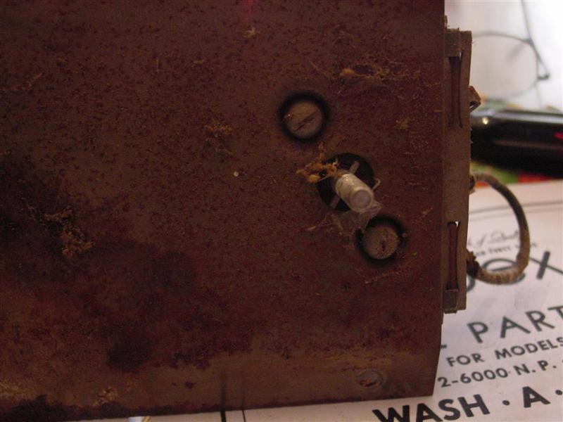
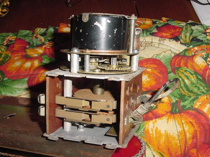
 Most of you will recall that Kevin recently picked up a very rare vintage Apex washer, one of only two known to club members. After years of neglect it needs a lot of tlc to get it going again. So after the initial clean up, since very little happens on a vintage machine without a functioning timer, Kevin decided to start there. From the outset, after years of sitting in a barn the timer was stuck solid. No movement was possible in either direction when the control knob was turned. Well, since I was to blame for letting him know about this washer in the first place, I figured I should offer to help sort out some of its problems. So back in November(I can’t believe it’s been that long) Kevin brought me the entire control panel with the timer attached so I could play with it. 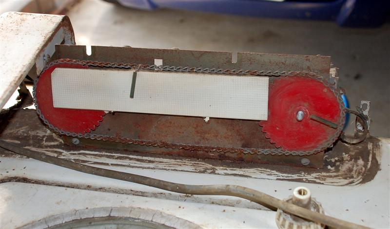
This post was last edited 01/31/2013 at 15:39 | ||

|
|
Post# 657202 , Reply# 1 1/31/2013 at 11:51 (4,094 days old) by d-jones (Western Pennsylvania (Pittsburgh Area)) |
||
|
| ||
|
Post# 657203 , Reply# 2 1/31/2013 at 11:52 (4,094 days old) by d-jones (Western Pennsylvania (Pittsburgh Area)) |
||
|
| ||
|
Post# 657205 , Reply# 3 1/31/2013 at 11:53 (4,094 days old) by d-jones (Western Pennsylvania (Pittsburgh Area)) |
||
|
| ||
|
Post# 657206 , Reply# 4 1/31/2013 at 11:54 (4,094 days old) by d-jones (Western Pennsylvania (Pittsburgh Area)) |
||
|
| ||
|
Post# 657207 , Reply# 5 1/31/2013 at 11:56 (4,094 days old) by d-jones (Western Pennsylvania (Pittsburgh Area)) |
||
|
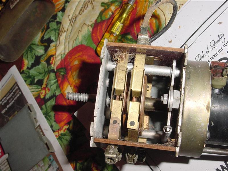
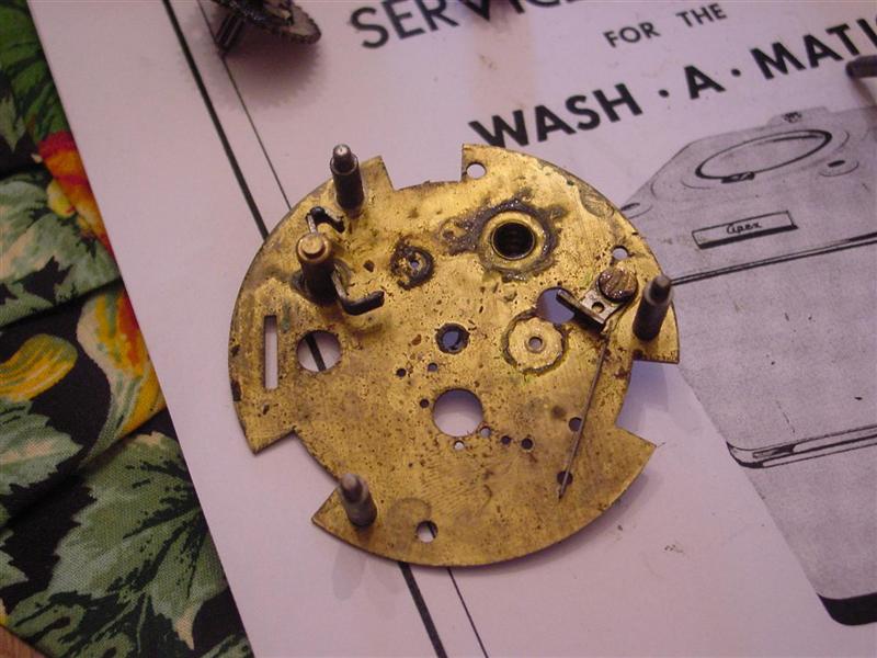
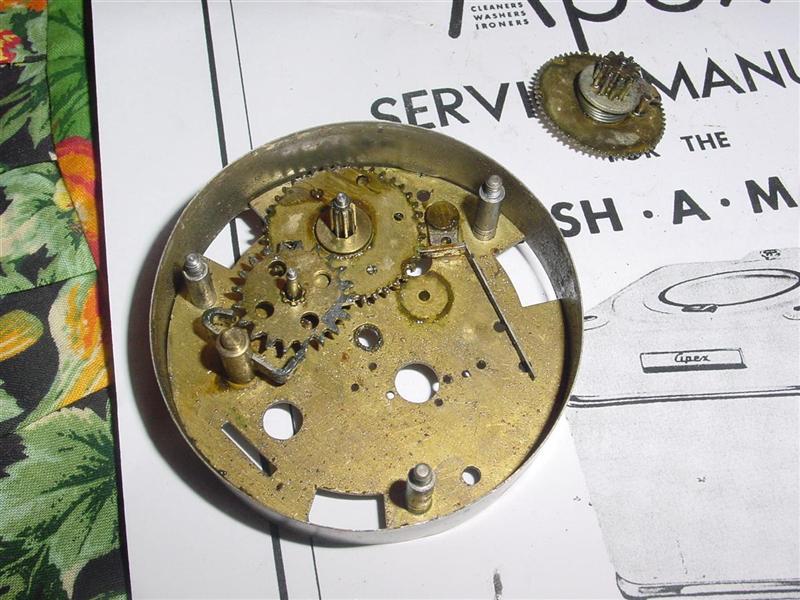
With the removal of three more pressed steel nuts, the top plate was free to be removed from the escapement. If you ever have to do this, do it slowly and get a good look at where things go as you�re taking it apart. Once the top cover is lifted off, things are pretty well free to move around in there, and they will. The more carefully you observe things at this point, the easier reassembly will be. As you can see, there isn�t much to see here other than a bit of coagulated grease, so I began to clean up the various little components figuring that when I got to the problem child it�d be obvious.
| ||
|
Post# 657208 , Reply# 6 1/31/2013 at 11:56 (4,094 days old) by d-jones (Western Pennsylvania (Pittsburgh Area)) |
||
|
| ||
|
Post# 657209 , Reply# 7 1/31/2013 at 11:57 (4,094 days old) by d-jones (Western Pennsylvania (Pittsburgh Area)) |
||
|
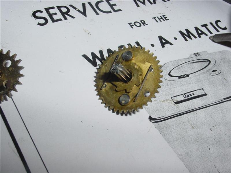
Here�s the trouble maker. This complicated little assembly of gears and springs allows the timer to drive the gear one way, while turning the control knob the other way will cause the small center gear to push the spring loaded pawls out of the way and slip past. This allows you to turn the cam assembly to the desired position without driving the escapement. These little pawls were being held firmly in place by old dried out lube that had literally glued them down. It took some effort, but they were freed up and new lube was applied.
| ||
|
Post# 657210 , Reply# 8 1/31/2013 at 11:58 (4,094 days old) by d-jones (Western Pennsylvania (Pittsburgh Area)) |
||
|
| ||
|
Post# 657211 , Reply# 9 1/31/2013 at 11:59 (4,094 days old) by d-jones (Western Pennsylvania (Pittsburgh Area)) |
||
|
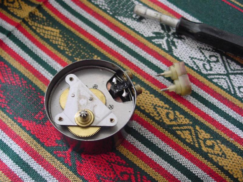
A quick check of the two timer motor terminals with an ohm meter revealed an open, so the darn motor was bad. I looked around a bit for a new motor, but for some reason vintage Ingraham clock motors from the early fifties are kind of hard to find,(imagine that) and when you do find them, the folks that have them are so proud of them that they wont let them go for less than one hundred and fifty dollars. Holly @#%&* batman! What do I do now?
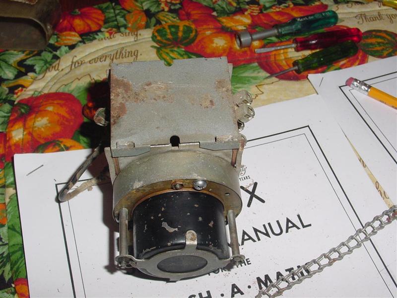
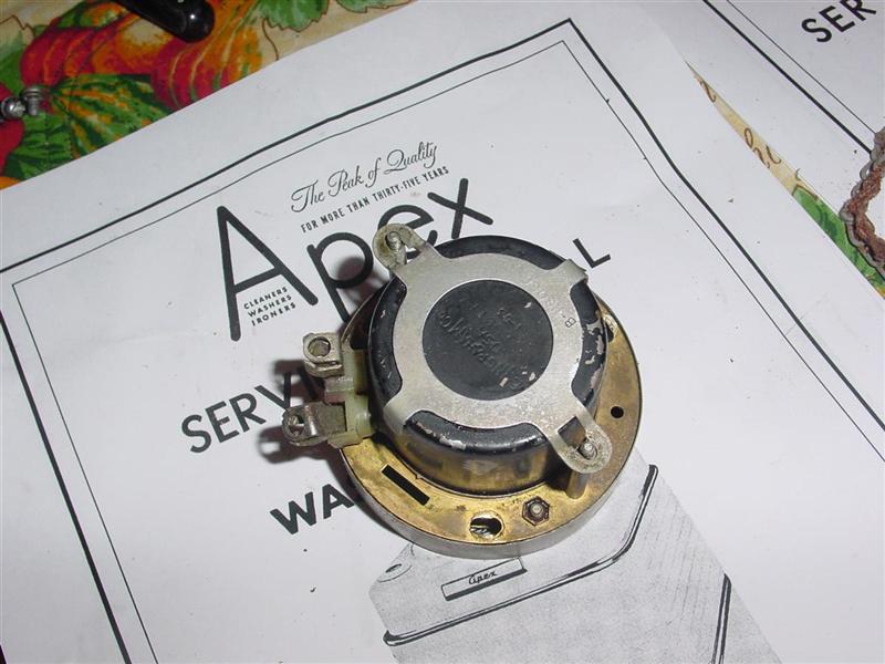
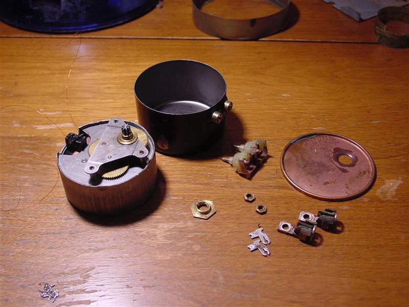
Well, I though about it for a while and tried to conjure up a way around this problem. I had another timer motor that looked like it might work, but it would require some modification of the escapement to get it mounted properly, and then I had an added problem in that I had no idea what the correct rpm should be. The stampings on the Ingraham motor made no mention of rpm. So if the new motor speed didn�t match the old one, Kevin�s Apex might end up running faster or slower than it was intended to. Rather than risk screwing things up I made the only choice I could. I�d just have to repair the original motor. With that in mind I began to disassemble it. This little nut is all that holds the cover plate on. 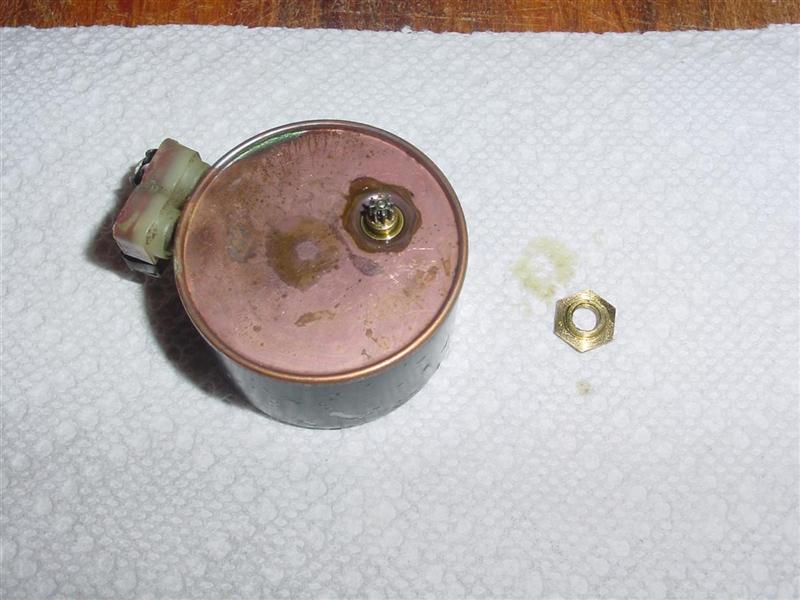
This post was last edited 01/31/2013 at 13:15 | ||
|
Post# 657212 , Reply# 10 1/31/2013 at 12:00 (4,094 days old) by d-jones (Western Pennsylvania (Pittsburgh Area)) |
||
|
| ||
|
Post# 657213 , Reply# 11 1/31/2013 at 12:01 (4,094 days old) by d-jones (Western Pennsylvania (Pittsburgh Area)) |
||
|
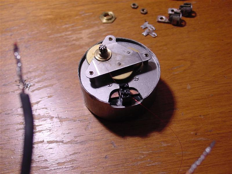
With the inner motor housing removed from the outer housing you finally get a good look at it. The top cover that holds the reduction gears is staked in place, so those stakes will need to be driven back to get the top plate off. This photo was taken during reassembly, but you get the idea. 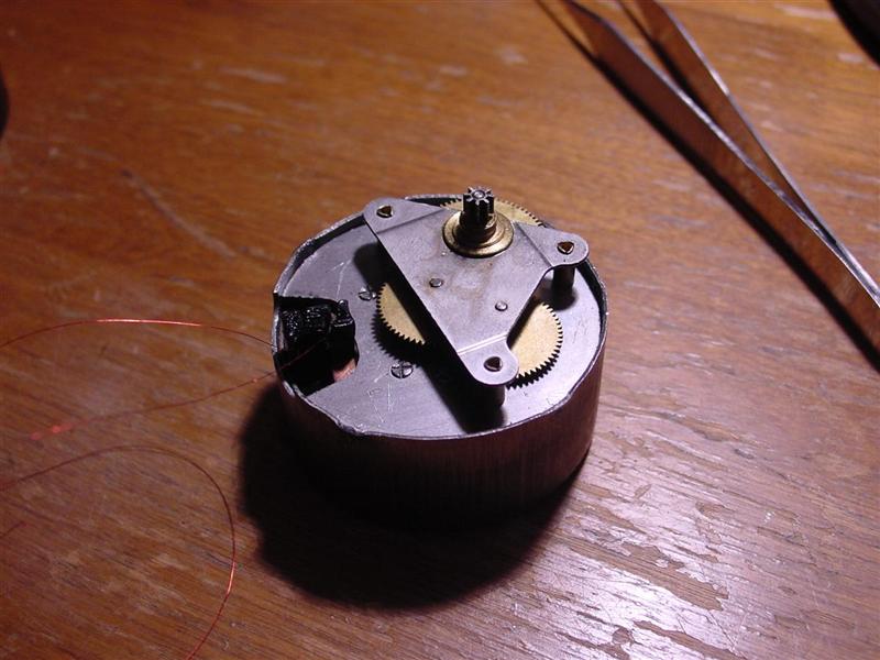
This post was last edited 01/31/2013 at 14:13 | ||
|
Post# 657215 , Reply# 12 1/31/2013 at 12:02 (4,094 days old) by d-jones (Western Pennsylvania (Pittsburgh Area)) |
||
|
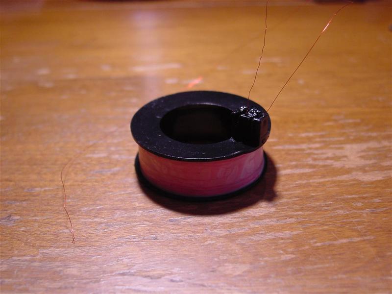
With the coil removed I began to unroll the wire onto a cardboard tube, thinking if I got lucky and found the break quickly, I could solder it back together and reassemble it. 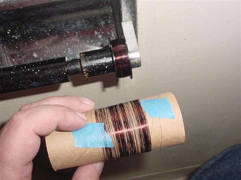
This post was last edited 01/31/2013 at 14:30 | ||
|
Post# 657216 , Reply# 13 1/31/2013 at 12:02 (4,094 days old) by d-jones (Western Pennsylvania (Pittsburgh Area)) |
||
|
WRONG!...........As I unrolled the wire I found break, after break, after break. It quickly got ridicules. Each piece of blue tape represents another break, so I gave up and ripped all the wire off the spool.
This post was last edited 01/31/2013 at 13:07 | ||
|
Post# 657217 , Reply# 14 1/31/2013 at 12:04 (4,094 days old) by d-jones (Western Pennsylvania (Pittsburgh Area)) |
||
|
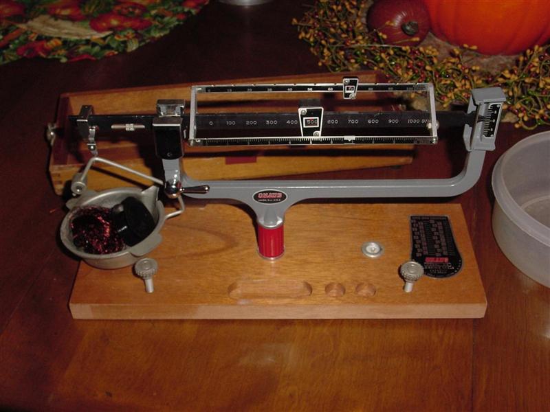
I was going to have to start over with new wire. But since I needed to know how much new wire to roll onto the spool, all of the old wire was carefully collected and weighed, along with the empty spool. The scale used was more than up to the job, and sensitive enough that when an overlooked piece of wire several inches long was found on the table and placed in the tray, the scale had to be readjusted for the extra weight.
| ||
|
Post# 657218 , Reply# 15 1/31/2013 at 12:05 (4,094 days old) by d-jones (Western Pennsylvania (Pittsburgh Area)) |
||
|
| ||
|
Post# 657219 , Reply# 16 1/31/2013 at 12:05 (4,094 days old) by d-jones (Western Pennsylvania (Pittsburgh Area)) |
||
|
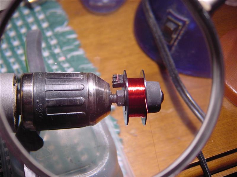
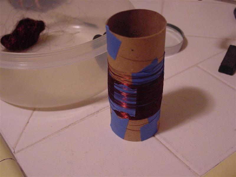
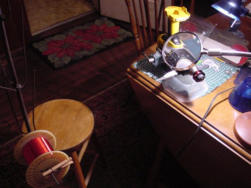
This is what the setup looked like. The battery for the drill motor needed recharging so this picture was taken while I waited for it to finish. Since the wire was thin enough that it was hard to see, the magnifying glass made it possible to monitor the progress. The wire was guided onto the spool by gripping it loosely between my thumb and index finger.
| ||
|
Post# 657220 , Reply# 17 1/31/2013 at 12:06 (4,094 days old) by d-jones (Western Pennsylvania (Pittsburgh Area)) |
||
|
| ||
|
Post# 657221 , Reply# 18 1/31/2013 at 12:07 (4,094 days old) by d-jones (Western Pennsylvania (Pittsburgh Area)) |
||
|
| ||
|
Post# 657222 , Reply# 19 1/31/2013 at 12:09 (4,094 days old) by d-jones (Western Pennsylvania (Pittsburgh Area)) |
||
|
| ||
|
Post# 657228 , Reply# 20 1/31/2013 at 12:59 (4,094 days old) by Jetcone (Schenectady-Home of Calrods,Monitor Tops,Toroid Transformers) |
||
DAVID!
That is FANTASTIC WORK! Now we can save all our timer motors. Amazing you found so many breaks in a spool locked inside a can never designed to be moved or touched! It has to be just plain age on the wire!
Now the cam with spring gear that you freed up, did it unwind when you took apart the escapement? If so it has to be clocked back a notch to put tension back on the spring otherwise the escapement won't work right. jon | ||
|
Post# 657229 , Reply# 21 1/31/2013 at 13:09 (4,094 days old) by chestermikeuk (Rainhill *Home of the RailwayTrials* Merseyside,UK) |
||
Wow | ||
| Post# 657237 , Reply# 22 1/31/2013 at 13:26 (4,094 days old) by redcarpetdrew (Fairfield, CA) | ||
Right on! | ||
|
Post# 657240 , Reply# 23 1/31/2013 at 13:36 (4,094 days old) by Ultramatic (New York City) |
||
Wow! | ||
|
Post# 657244 , Reply# 25 1/31/2013 at 13:44 (4,094 days old) by d-jones (Western Pennsylvania (Pittsburgh Area)) |
||
|
Jon I wondered about all those breaks myself. It's a real head scratcher. All I can say for certain is that it didn't break while I was unrolling it. The broken ends would just slip off the spool without even the slightest hint of a tug. While trying to find a way around the dead timer motor problem, I managed to find a local outfit that had a timer assembly that used the very same motor. They wanted eighty dollars for it, but before I would even consider it I asked them to put a meter on the motor leads and see if it was good. It wasn't. Somehow, while just sitting in its box on the parts shelf for the last few decades it developed an open. So I guess this is more common than I would have thought. | ||
|
Post# 657245 , Reply# 26 1/31/2013 at 13:44 (4,094 days old) by kb0nes (Burnsville, MN) |
||
Bravo!! | ||
| Post# 657276 , Reply# 27 1/31/2013 at 14:33 (4,094 days old) by norgeway (mocksville n c ) | ||
|
Scale.. That scale is very similar to what my Dad used loading rifle shells.The powder must be weighed exactly! | ||
| Post# 657291 , Reply# 28 1/31/2013 at 15:04 (4,094 days old) by christfr (st louis mo) | ||
 | ||
|
Post# 657294 , Reply# 29 1/31/2013 at 15:14 (4,094 days old) by d-jones (Western Pennsylvania (Pittsburgh Area)) |
||
|
David (recyclewasher) The scale used here is intended for reloading ammunition, so it's calibrated in grains. But any sensitive and accurate scale would work fine. In this case, the weight of the old wire and the empty spool was 576.6 grains, and the weight of the spool loaded with new wire was 576.7 grains. Close enough.
As for the wire, believe it or not, my dad had that big spool of wire sitting on a shelf in his bedroom.(that's just how he is) He retired from the Department of Water and Power here in Los Angeles, and the DWP does almost all of their own maintenance, including rewinding electrical solenoids and motor windings. They have machines that turn the spools that the wire is being fed onto, and since they can't have the wire run out before the spool is fully loaded, once the spools that are supplying the new wire get below a certain point, they're set aside for scrap or small projects. My dad bought one and brought it home years ago. I just got lucky in that it turned out to be the exact same wire that I needed for this little job. The label on the end of the spool identifies it as number 39 wire, which should be .0035 inches in diameter, but the wire actually measured out to .0041 inches. I'm going to guess that the difference is the thickness of the varnish applied to the wire.
The nut drivers belonged to my grandfather who was a TV and radio repairman in the fifties and sixties. They came in a small set and were made by Xcelite. They've been very handy over the years. Do you by any chance have the same set? | ||
| Post# 657319 , Reply# 31 1/31/2013 at 16:51 (4,094 days old) by maytagman (Half Moon) | ||
|
timer motor repair You could go into business repairing timer motors for all of us on here. My bendix timer motor is bad. Just a thought. Thanks, Don | ||
| Post# 657330 , Reply# 32 1/31/2013 at 17:38 (4,094 days old) by in2itdood () | ||
|
Totally amazed! WOW ... with this type of progress, I sure hope Kevin can get that super cool machine up and running! Hats off to David for your timer efforts! | ||
| Post# 657332 , Reply# 33 1/31/2013 at 17:53 (4,094 days old) by redcarpetdrew (Fairfield, CA) | ||
|
Xcelite | ||
|
Post# 657333 , Reply# 34 1/31/2013 at 17:55 (4,094 days old) by turquoisedude (.) |
||
 | ||
| Post# 657345 , Reply# 35 1/31/2013 at 19:48 (4,094 days old) by StrongEnough78 (California) | ||
|
| ||
| Post# 657353 , Reply# 36 1/31/2013 at 20:37 (4,094 days old) by Whirlaway (Hampton Virginia) | ||
|
Fantastic I didnt know that people like you still existed!!!!!!!! How wonderful you are to do this!!!!! Good for YOU !!! Bobby | ||
|
Post# 657456 , Reply# 37 2/1/2013 at 11:40 (4,093 days old) by combo52 (50 Year Repair Tech Beltsville,Md) |
||
Timer Motor Rewinding WOW David that was a very impressive repair. It is interesting to me that we are seeing so many of that style timer motor failing these days. Back 30+ years ago we almost never saw these early black motors fail, it must be that their was some deterioration of the motor wire insulation that time is taking its toll on. The thing that I have been doing when I see these black timer motors fail is to mount the next generation silver motor on the escapement, these newer motors were a proper replacement and were used all through the 1960s and into the 70s and are still around.
On today's machines with the better quality control and better manufacturing processes I suspect that things like this will not fail after 60 years nearly so often, BUT the electronics will be the parts that fail in today's machines over time and they may or may not be so possible to fix, Time Will Tell, John. | ||
| Post# 657464 , Reply# 38 2/1/2013 at 12:26 (4,093 days old) by cadman (Cedar Falls, IA) | ||
For those looking for this type of wire...years ago I was building a TV set and needed some very fine, very specific gauge wire like this to wind my IF coils. A local motor shop was more than happy to sell me a few small spools of exactly what I needed, but I had to try a few places first. Seems motor re-winding, even for specialized shops, is one more thing that's gotten to be "too much trouble" and is outsourced. -Cory
| ||
|
Post# 657568 , Reply# 39 2/2/2013 at 03:21 (4,093 days old) by d-jones (Western Pennsylvania (Pittsburgh Area)) |
||
|
Sorry I took so long to finish this up,but here goes. The odd looking flat pieces of metal that tied the fine coil wire to the large power leads were going to be too difficult and risky to use again. They originally sat in slots in the black plastic block with a short piece of wire lead crammed into the hole below them, then they were sealed in place by melting the black plastic and spreading it over the top of the slot. You can see the way they were installed in reply 10 if you’re curious. That sort of thing seldom works more than once, and I was really worried about breaking the little wire leads. So I did this instead. It’s not pretty but it works, and with any luck, nobody will ever have a reason to be in there again. “Fingers crossed” 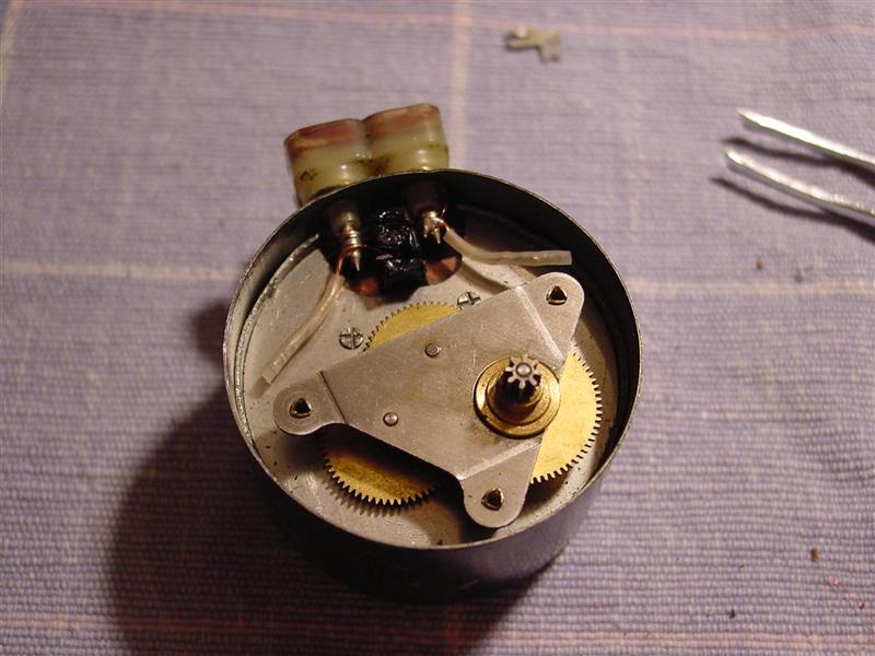
| ||
|
Post# 657569 , Reply# 40 2/2/2013 at 03:23 (4,092 days old) by d-jones (Western Pennsylvania (Pittsburgh Area)) |
||
|
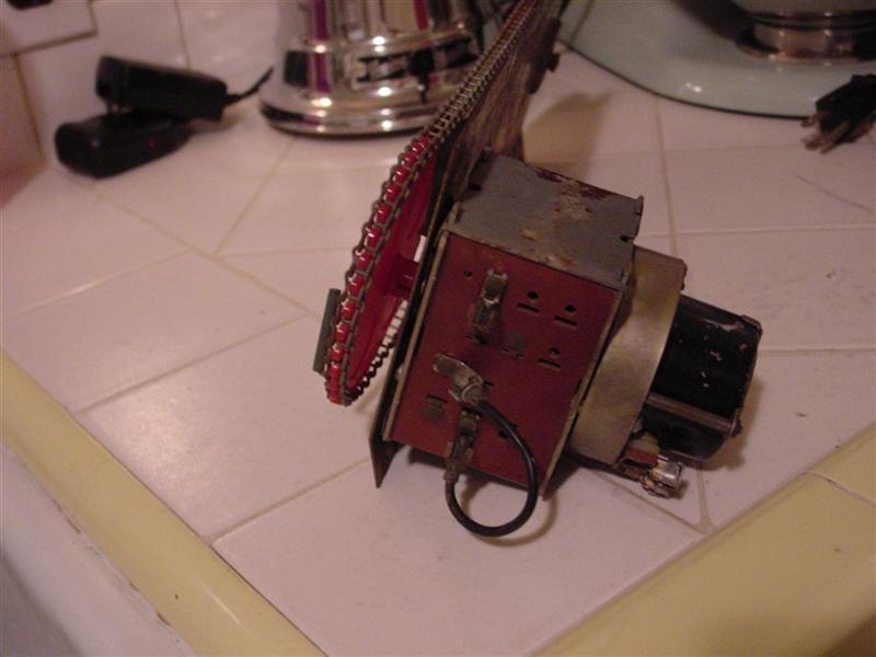
Finally reunited with the escapement, it sat here on the counter with power applied for about half an hour while I watched it work. After Jon's comment above regarding the spring loaded gear in the escapement I wanted to be sure I had it right. Thankfully, everything seemed to be fine, so I decided it was time to finish putting it back together. 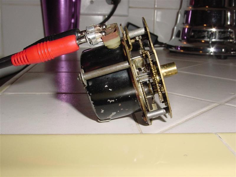
This post was last edited 02/02/2013 at 04:34 | ||
|
Post# 657570 , Reply# 41 2/2/2013 at 03:26 (4,092 days old) by d-jones (Western Pennsylvania (Pittsburgh Area)) |
||
|
| ||
| Post# 657574 , Reply# 42 2/2/2013 at 04:29 (4,092 days old) by fido () | ||
|
Having repaired a few relatively modern timers I can appreciate the attention to detail and dexterity needed to do this repair, congratulations! | ||
| Post# 657582 , Reply# 43 2/2/2013 at 05:51 (4,092 days old) by toploader55 (Massachusetts Sand Bar, Cape Cod) | ||
You have the Patience of a Saint | ||
|
Post# 657589 , Reply# 44 2/2/2013 at 08:05 (4,092 days old) by Jetcone (Schenectady-Home of Calrods,Monitor Tops,Toroid Transformers) |
||
|
David
How did you attack the staking, did you use fine needle nose pliers to pinch the staking?
And McMasterCarr lists up to 36AWG if anyone is interested. WireSource on Amazon sells 39AWG. jon Now Kevin you've really got to throw your butt into gear!!! Wash In next April?? This post was last edited 02/02/2013 at 08:21 | ||
|
Post# 657595 , Reply# 45 2/2/2013 at 08:45 (4,092 days old) by Unimatic1140 (Minneapolis) |
||
Very impressive David, I find those little black Ingraham motors fail all the time on machines that sit un-powered for a long time. It seems the key to keeping them running is actually using them.
I usually replace them with more modern timer motors from the 60's and 70s, but sometimes the escapement mounting has to be modified for them to fit. This will be a very good reference for the future! Thanks for taking the time to document this. | ||
|
Post# 657655 , Reply# 46 2/2/2013 at 14:44 (4,092 days old) by d-jones (Western Pennsylvania (Pittsburgh Area)) |
||
|
Thanks for all the comments, everyone! I have to admit though, when I first offered to fix the Apex's timer I had no idea it would lead to rewinding a motor. But when it turned out that the motor was bad I figured I'd at least look into it. After all, it was already dead, so it certainly couldn't hurt to look. Things just sort of took off from there, and as it turns out, the motor was only "mostly dead."
One of the main reasons I wanted to try this is that original parts, and even suitable replacements, are steadily disappearing from parts shelves all over the country. Some are being purchased and used, but quite a few are simply being thrown away under the mistaken assumption that nobody wants them anymore. I've encountered this several times myself. I'll walk in to an appliance shop that's been around for decades and tell them what I'm looking for, only to hear the guy tell me that I should have stopped by a couple of years ago. They had boxes and boxes of that stuff that they threw away. This is going to lead to a serious parts shortage one of these days, and for some machines it already has. Consequently, in order to keep our vintage machines going we're going to have to find ways to work around this problem. Some are already heading in that direction with discussions about having certain parts made, and for some parts that really is the only solution. But for quite a few parts, if we can find ways to repair them and keep them going a bit longer then we've scored a minor victory of sorts. As you can see, none of the tools I used in this repair are high tech or all that hard to come by, and yet they worked out. So anyone else that wanted to do this shouldn't have too much trouble assembling everything they'd need. Some of you may already have ideas about ways to improve the process.
Jon - The staking had originally been applied with a center punch, creating a small dimple in the motor housing that extended over the top plate(the one with the gears mounted to it) in four places. I had to use very strong pointed needle nose pliers to bend these out of the way. They could have been reinstalled with a punch, but instead I used a very small hammer to bend the housing above the top plate inward slightly at each of the previous stake points. It seemed to work. I hope this helps. Are you thinking of having a go at this with one of your timer motors? | ||
|
Post# 658064 , Reply# 47 2/4/2013 at 14:10 (4,090 days old) by RevvinKevin (Tinseltown - Shakey Town - La-La Land) |
||
|
I found break, after break, after break...... in fact OVER 1 | ||
|
Post# 658083 , Reply# 48 2/4/2013 at 17:06 (4,090 days old) by d-jones (Western Pennsylvania (Pittsburgh Area)) |
||
|
Kevin | ||
| Post# 658121 , Reply# 49 2/4/2013 at 20:58 (4,090 days old) by badgerdx () | ||
|
I have to add my "WOW". My old industrial arts teacher would have "Bust his buttons" over you. No doubt. | ||
|
Post# 658125 , Reply# 50 2/4/2013 at 22:30 (4,090 days old) by Jetcone (Schenectady-Home of Calrods,Monitor Tops,Toroid Transformers) |
||
|
Yes David
You have inspired us , I am going to have a go at it now. I rebuilt two escapements last summer first time I've ever done that. And this looks like fun. I have ordered the wire today. I'll need to get a scale next, I have a digital scale I wonder if that will be accurate enough, it only goes up to 200 grams.
I think Robert is going to try it too. | ||
|
Post# 658137 , Reply# 51 2/5/2013 at 01:05 (4,090 days old) by d-jones (Western Pennsylvania (Pittsburgh Area)) |
||
|
Jon - if you're going to tackle this then let me pass on a little more info that might be useful. The plastic spool is kept centered in the motor housing by twelve metal posts. Six are mounted to the floor of the housing, while six are mounted to the top plate. All are mounted in pairs spaced 120 degrees apart, and each one has a small metal peg protruding from the exposed end that fits into a corresponding hole on the opposite plate. I'm pretty sure that when these were made the metal plates with all the posts would have been assembled on the plastic spool prior to being installed in the motor housing. Then the lower plate was riveted in place through the bottom of the housing. Now because of those rivets, the lower plate will stay behind fixed to the floor of the housing and only the upper plate with its six posts will come out. Be very careful that you keep that upper plate level as you withdraw it from the center of the plastic spool. The fit is quite snug, and if one of those posts should become bent then reassembly will be difficult. They're too thick to bend in the middle, but you'll want to watch out for the spot were they mount to the upper plate. If one or more of them should get off kilter then its little peg won't line up with its hole. Though I suppose that if that were to happen you might be able to remove the rivets that hold the lower posts in place and go from there, but I'm getting ahead of myself now. I should have taken a picture or two of all that but somehow I completely overlooked it. At least now you know, so you'll be prepared for it. Best of luck to you.
PS. If you look at reply 39 you can see the ends of two of the posts I'm talking about. They're staked into place in the top plate with a rather crude x pattern. | ||
|
Post# 658167 , Reply# 52 2/5/2013 at 07:13 (4,089 days old) by Unimatic1140 (Minneapolis) |
||
|
I'm curious how critical the amount of copper wire rolled onto the spool is? Of course too little and the rotor will not turn, but if you added lets say 25% more, would it affect the rotation of the rotor at all? These synchronous clock motor rotors turn at the same speed because of the 60 cycle alternating current, that is why an analog/mechanical electric clock keeps such accurate time, either they work or they do not work at all but they are never slower or fast, always just right.
| ||
|
Post# 658174 , Reply# 53 2/5/2013 at 07:55 (4,089 days old) by Jetcone (Schenectady-Home of Calrods,Monitor Tops,Toroid Transformers) |
||
|
With synchronous motors
they always went by the number of winds on the spool, thats how they maintain accuracy. Clocks have to be very accurate but our timer motors not so much I think. I used to have a book on how to rewind small fractional horsepower motors, I'll dig for it , it may have a section on synchronous motors.
Dave, thanks for the tips!! I thought the stakes you removed were those post tops, no? I see them there, they are cross hatched so there are 4 more under the gearing?? jon | ||
|
Post# 658176 , Reply# 54 2/5/2013 at 08:19 (4,089 days old) by gansky1 (Omaha, The Home of the TV Dinner!) |
||
 | ||
|
Post# 658186 , Reply# 55 2/5/2013 at 10:42 (4,089 days old) by kb0nes (Burnsville, MN) |
||
|
Ideally one would replace the winding with the same number of turns to keep the coil inductance fairly constant. I don't think a minor variance will result in any harm. Too much or too little winding may result in the motor torque performance changing. I believe that as Robert states, the motors are synchronous so their rotational speed is determined by the number of poles and the line frequency. Variation in winding fill won't change this.
David's use of the scale to weight the wire was very clever since he had to deal with all the breaks making turn counting or measuring wire length difficult. If the length could be measured (or the number of turns counted) as the wire is payed off the bobbin then this would be a more accurate way of determining the amount of wire to wind back on. | ||
| Post# 658189 , Reply# 56 2/5/2013 at 10:54 (4,089 days old) by recyclewasher () | ||
|
and don't FORGET!... the all important WOODEN CLOTHESPIN and 'modified' COAT RACK for the bobbin improv... gotta love this project.. | ||
|
Post# 658199 , Reply# 57 2/5/2013 at 12:08 (4,089 days old) by d-jones (Western Pennsylvania (Pittsburgh Area)) |
||
|
Jon - Those two stakes you see are indeed the ends of two of the metal posts. Each of them has a companion sitting just out of sight, and then two more are completely hidden from view under the gear assembly. I didn't tamper with them at all. The stakes I had to remove were in the housing itself and held the top plate in place by gripping its edge in four places. Once you get into your project you'll quickly see what I'm talking about.
David - A modified coat rack would be funny enough, but that device isn't a coat rack. It's actually a "bottle tree," meant to display colored glass bottles outside were the sunlight can shine through them. You simply slip the bottles over the wires and they sit there upside down. My sister gave it to my dad for Christmas this past year because he has lots of colored glass bottles he won't get rid of. When pressed on the issue he simply replies "but they're neat," and then holds one up to the light to admire the colored glass. Again, you'd have to know my dad.
As for the use of the scale to determine how much wire to use, Phil is right. Counting turns wasn't practical with all the breaks in the wire, but if you wanted to go that route, there are devices you can purchase that are made for winding coils and they come with a built in counter. If I was planning to do a lot of these I'd probably buy one. A search on Google using the term "coil winder" will lead you to them. | ||
|
Post# 658233 , Reply# 58 2/5/2013 at 15:01 (4,089 days old) by d-jones (Western Pennsylvania (Pittsburgh Area)) |
||
|
How much wire? Robert - I think the little motors would be pretty tolerant of minor variations in the number of turns, but I don't have a clue what 25% more wire than needed would do. I'll just defer to Phil's answer above.
Considering how many turns of wire there are in these coils, into the thousands actually, weighing them is probably a better option than counting turns. I think you'd be surprised at how accurate weighing can be with the right scale. When rewinding coils like these that use such fine wire, the guys at the DWP here in LA always go by weight. They say it just isn't worth the hassle of counting. | ||
|
Post# 658601 , Reply# 59 2/6/2013 at 20:28 (4,088 days old) by washerlover (The Big Island, Hawai�i) |
||
 | ||
| Post# 707608 , Reply# 60 10/6/2013 at 18:04 (3,846 days old) by statomatic (France) | ||
 | ||
| Post# 753714 , Reply# 62 4/29/2014 at 13:36 (3,641 days old) by ken (NYS) | ||
Bump | ||
|
Post# 753746 , Reply# 63 4/29/2014 at 17:36 (3,641 days old) by turquoisedude (.) |
||
|
Funny you mention timer motors...
I am bordering on desperation over those Ingraham timer motors these days... I have three dead ones and I had to pluck a good one out of a working machine to save another...
David, if you are willing to take on the rewinding a few, please let me know. I am very serious about this and I will pay for your services, of course! | ||
|
Post# 753768 , Reply# 64 4/29/2014 at 20:35 (3,641 days old) by jetcone (Schenectady-Home of Calrods,Monitor Tops,Toroid Transformers) |
||
|
This is a good thread | ||
| Post# 753769 , Reply# 65 4/29/2014 at 20:41 (3,641 days old) by ken (NYS) | ||
|
@Jon | ||
|
Post# 753773 , Reply# 66 4/29/2014 at 22:21 (3,641 days old) by d-jones (Western Pennsylvania (Pittsburgh Area)) |
||
|
Wow guys, thanks for tuning into this thread again after so much time has passed. It's nice to see that it hasn't been forgotten. I've also wondered if anyone else had decided to give this a try, so if anyone did, please chime in and let us know how it went.
Paul, I've actually been wondering if this repair would be repeatable. As I mentioned higher up in the thread, that plate with the six metal posts attached to it could have been really difficult to reassemble, but it wasn't, so now I worry that I just got lucky. Consequently, I think I'd like a chance to try this again. If I remember correctly I believe I even asked Robert if he had any dead ones laying about that I could work on, but as fate would have it he didn't so I just let it go. Anyways, send me a message through the private message system and let me know what you have in mind. This post was last edited 04/29/2014 at 22:58 | ||
|
Post# 753813 , Reply# 67 4/30/2014 at 07:37 (3,640 days old) by combo52 (50 Year Repair Tech Beltsville,Md) |
||
|
Old Black Timer Motors
These old timer motors that were made by the E.Ingraham Co. seem to be failing as time has gone on, back in the 60s-70s it seemed that we seldom saw one of these motors fail. The early motors made in the late 40s had the cover soldered in place, and between 9-49 and 11-49 they stared to have an easily removable cover that was held in place by the brass nut around the pinion shaft.
It seems that there was some type of contamination during manufacturing of these motors that is causing the copper windings to corrode and fail over time. I guess this is not surprising as most items manufactured in this time period were not made nearly as well as items are made today, we should get the E. Ingraham Co. to do a recall of these poorly made motors, LOL. The good news is that the later smaller silver motor design that came out in the mid 50s is a perfect fit on these older timers and so far this newer design TM does not seem to be failing like the earlier ones. Because the newer TMs fit my older machines I personally have no need to try to fix these old black ones. David I think it was quite an achievement that you successfully fixed one of these early motors and if you want more of them I have a whole pile of ones that have no motor continuity, let me know and I will send you some, otherwise they will eventually end up in the metal recycling bin. John L. | ||
| Post# 753822 , Reply# 68 4/30/2014 at 08:52 (3,640 days old) by ken (NYS) | ||
|
@John
How do you go about finding the correct newer silver timer motor for a particular application to replace an older black one? Is it all done by cross referencing the original TM part number?
Say for example you have a 1950s Kenmore washer with a dead timer motor. Ive read that newer Whirlpool timers will work but up to what year? And is it all models or only certain models? | ||
|
Post# 754073 , Reply# 69 5/1/2014 at 06:32 (3,639 days old) by combo52 (50 Year Repair Tech Beltsville,Md) |
||
|
Timer Motor Replacement
Hi Ken, I just use the next generation timer motor that was used on Mallory timers, they were used starting on machines in the mid 50s and on into the 60s and well beyond in many machines. This newer design motor has the power leads coming out of the TM casing instead of having two terminals on the side of the TM that the power plugs into. All you have to do to install these newer motors is splice the power wires and turn the orignal mounting plate that held the orignal TM to the escapement upside down and reinstall the two tiny nuts that hold it in place.
Part #s for this are probably fairly useless as almost every one of them is NLA if you try to look them up that way. | ||
|
Post# 754148 , Reply# 70 5/1/2014 at 11:59 (3,639 days old) by d-jones (Western Pennsylvania (Pittsburgh Area)) |
||
|
John | ||
|
Post# 755849 , Reply# 71 5/9/2014 at 01:18 (3,632 days old) by jetcone (Schenectady-Home of Calrods,Monitor Tops,Toroid Transformers) |
||
|
Yes | ||
| Forum Index: | 
| Other Forums: |

|

|

|

|

|

 Comes to the Rescue!