|
Thread Number: 49405
WHP Catalyst wonky recirc valve |
[Down to Last] |
Post# 714575 11/11/2013 at 12:16 (3,817 days old) by DADoES  (TX,�U.S. of A.) (TX,�U.S. of A.) |
||
|
�
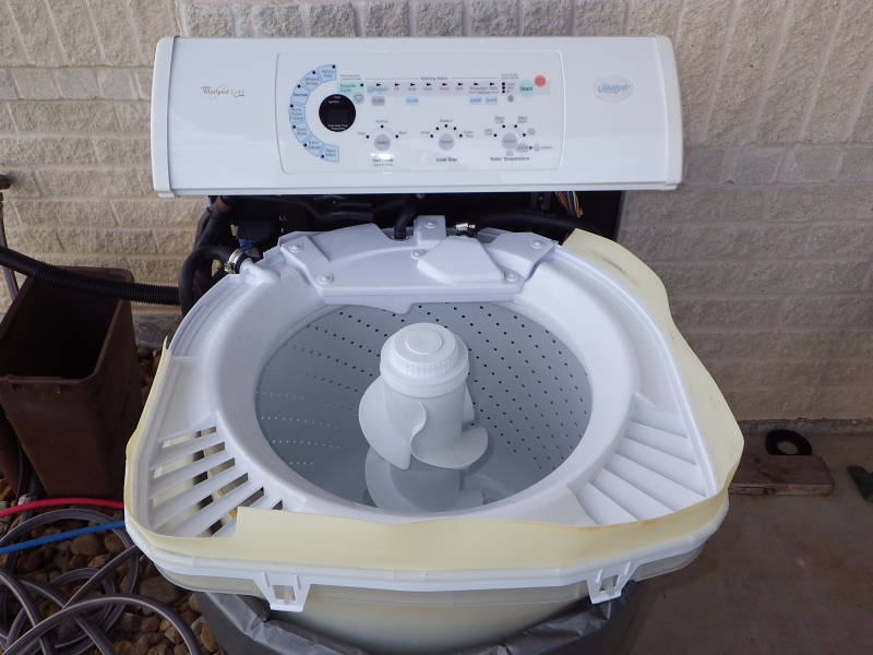
The recirc/drain valve seems to not always release at end of a cycle.� Remains energized into the next cycle and thus drains the water if a catalyst treatment is involved and throws an F4 fault.� Only way to reset the valve is pull the power cord. I can make the issue occur for sure by running a spin-only, press pause, restart it ... if then canceled (press pause twice), OR at end of the spin, the valve does not release.� If a spin-only is started and canceled (without a pause & restart first), the valve does release.� A weird software bug? I'm running a full cycle to normal completion now to check what happens. Is failure of the drain valve to release (unless/until the power cord is disconnected) an indication of a bad valve, or a problem with the control board?� The board sends power to the valve, the valve doesn't internally generate its power, right? | ||
|
|
Post# 714581 , Reply# 1 11/11/2013 at 12:44 (3,817 days old) by DADoES (TX,�U.S. of A.) |
||
|
| ||
|
Post# 714623 , Reply# 2 11/11/2013 at 15:20 (3,817 days old) by DADoES (TX,�U.S. of A.) |
||
|
| ||
| Post# 714682 , Reply# 3 11/11/2013 at 18:19 (3,816 days old) by repair-man (Pittsburgh PA) | ||
|
I have experienced the recirculate valves stick in the drain position. Of course a new valve solved the problem. | ||
|
Post# 714709 , Reply# 4 11/11/2013 at 19:45 (3,816 days old) by DADoES (TX,�U.S. of A.) |
||
|
| ||
|
Post# 714852 , Reply# 6 11/12/2013 at 11:49 (3,816 days old) by DADoES (TX,�U.S. of A.) |
||
|
| ||
|
Post# 714853 , Reply# 7 11/12/2013 at 11:52 (3,816 days old) by kb0nes (Burnsville, MN) |
||
It's also possible output device that does the switching on the control board is doing something funky.
If its a solid state Triac it could just be remaining in a conducting mode even after it shouldn't. Perhaps even partially allowing enough current to flow to keep the valve open as Ed mentioned. I'd attempt to trace the wire to the controller connector then trace back on the PCB to find the switching device. Then you should be able to determine what they use for switching. It could be a Triac, a solid state relay or a mechanical relay. It may be easy to swap that part to effect a repair. If you can determine the device on the board you think is doing the switching post any markings on the device or a photo. Most control board failures are due to either power supply issues or the output switching device failing and are reasonably easily repairable. I have salvaged a few furnace boards by simply swapping a common component. | ||
|
Post# 714888 , Reply# 8 11/12/2013 at 16:11 (3,816 days old) by DADoES (TX,�U.S. of A.) |
||
|
�
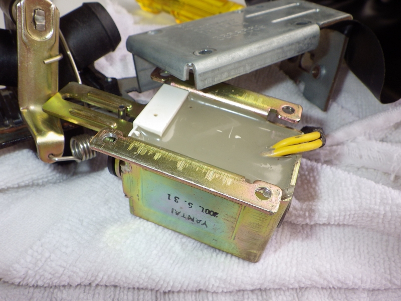
I ordered a replacement valve (overnight shipping, it's an urgent situation), but I'm thinking again that the valve is not the problem. It has a strong release spring, and does not stick when I manually press and hold it into actuated position.� Springs back immediately and strongly when I let go of it. Info gathered elsewhere says the valve is DC-powered, has an onboard rectifier.� But that wouldn't be the direct source of "holding" current, it has to come from the control board. I have no experience tracing/troubleshooting electronic boards. 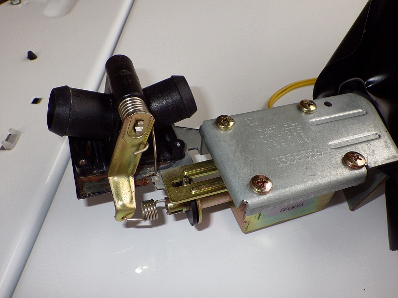
| ||
|
Post# 714889 , Reply# 9 11/12/2013 at 16:12 (3,816 days old) by DADoES (TX,�U.S. of A.) |
||
|
| ||
|
Post# 714892 , Reply# 10 11/12/2013 at 16:13 (3,816 days old) by DADoES (TX,�U.S. of A.) |
||
|
| ||
|
Post# 714893 , Reply# 11 11/12/2013 at 16:14 (3,816 days old) by DADoES (TX,�U.S. of A.) |
||
|
| ||
|
Post# 714894 , Reply# 12 11/12/2013 at 16:15 (3,816 days old) by DADoES (TX,�U.S. of A.) |
||
|
| ||
|
Post# 714900 , Reply# 13 11/12/2013 at 16:48 (3,816 days old) by kb0nes (Burnsville, MN) |
||
|
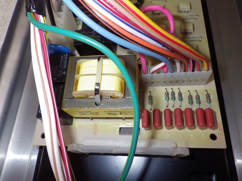
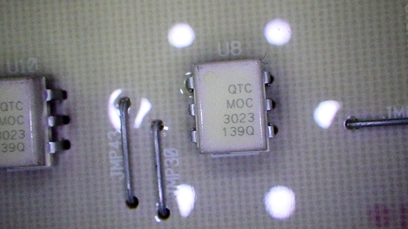
My suspicion is that the valve coil is being driven by one of those six white 6-legged IC's. You'd have to follow the trace on the backside of the board from the pin on the connector to figure which device it is.
My guess is that the IC's are Triac output optical couplers. Its quite possible that the one that drives that relay has become "leaky". Could you read the part ID on one of those IC's and share it? Also is there an identifying part number on the PC board itself?? | ||
|
Post# 714904 , Reply# 14 11/12/2013 at 17:01 (3,815 days old) by DADoES (TX,�U.S. of A.) |
||
|
| ||
|
Post# 714907 , Reply# 15 11/12/2013 at 17:02 (3,815 days old) by DADoES (TX,�U.S. of A.) |
||
|
| ||
|
Post# 714908 , Reply# 16 11/12/2013 at 17:11 (3,815 days old) by DADoES (TX,�U.S. of A.) |
||
|
| ||
|
Post# 714914 , Reply# 17 11/12/2013 at 17:28 (3,815 days old) by kb0nes (Burnsville, MN) |
||
|
Motorola MOC3023
Indeed the IC's are a opto isolators that have a small Triac output device designed to isolate and drive a larger Triac. Its a bit unconventional to use these to directly switch a load, although it could be done if the current draw was fairly small.
Pins 1 & 2 are for an internal infrared LED which will optically turn on the output Triac when ~3v is applied across the LED. Pins 4 & 6 are essentially the AC "switch" that will turn on a current path to drive your valve relay. I don't know if you are comfortable with measuring voltages on the IC's or not but if you were you should see the LED drive voltage drop off when the valve isn't energized and the output AC voltage _should_ drop off at the same point. A failure of the device could make it leak. DigiKey sells the IC's for $.68 each, but you'd have to be comfortable with reworking the board. Not sure any of this helps but its more information for possible understanding :) 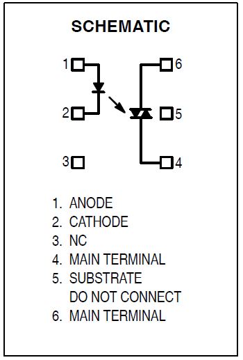
| ||
|
Post# 714917 , Reply# 18 11/12/2013 at 17:47 (3,815 days old) by DADoES (TX,�U.S. of A.) |
||
|
�
Put it this way ... I did several small Heathkit projects years ago, am game to try.� Problem is this machine goes in one of my neighbor's rental properties.� New people move in Sat so he wants it back before then.� They have a washer but he doesn't want them to move it in for fear they'd be satisfied it could stay and he'd have this machine to store somewhere ... and possibly the matching dryer if they'd want to move theirs in as well.� It is usable other than the valve sticking, which comes into play only on cycles that use the Catalyst treatment, so I suppose fixing this is not mandatory, perhaps a project at the next renter turnover. This week has been a huge ruckus on multiple fronts. | ||
|
Post# 714924 , Reply# 19 11/12/2013 at 18:14 (3,815 days old) by kb0nes (Burnsville, MN) |
||
|
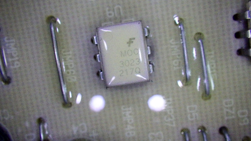
Did a bit of digging on the board itself. I managed to find a tiny photo of the bottom of the PCB so I could follow the traces.
The IC that feeds the 2nd pin from the left on the connector is U10, the center one closest to the board edge. Pin 6 feeds the connector. You could measure AC voltage on this pin during operation, it should drop near zero when the solenoid coil is not energized. Pin 4 should be AC hot all the time. The IC itself is common, you can get them at most any electronics house, Digi-Key, Mouser, Newark etc. 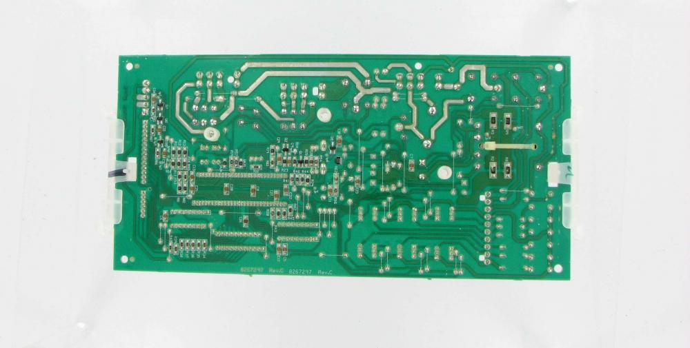
| ||
| Post# 714927 , Reply# 20 11/12/2013 at 18:30 (3,815 days old) by thefixer () | ||
|
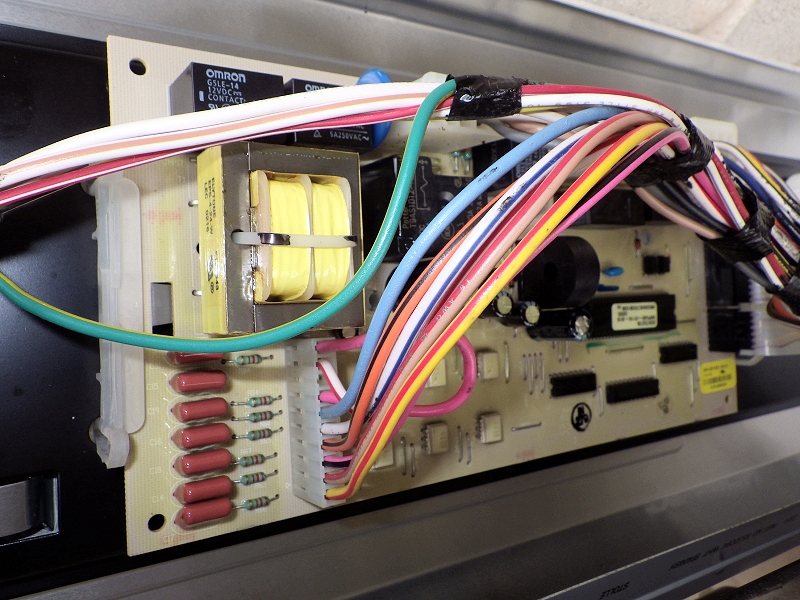
The 6 optocouplers are used for the other 6 valves in the washer (bleach, fresh, fabric softener, detergent, hot, cold). The diverter valve receives power via the outboard relay above the transformer. | ||
| Post# 714928 , Reply# 21 11/12/2013 at 18:44 (3,815 days old) by thefixer () | ||
|
Here's the circuit trace for pin 2 CLICK HERE TO GO TO thefixer's LINK 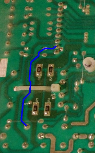
| ||
| Post# 714934 , Reply# 22 11/12/2013 at 19:22 (3,815 days old) by thefixer () | ||
|
Actually, it's pin 9 of connector P6 | ||
|
Post# 714935 , Reply# 23 11/12/2013 at 19:28 (3,815 days old) by kb0nes (Burnsville, MN) |
||
|
Hold the presses, indeed my board orientation was in error!! I hate working without a board in hand. Thanks to ?? (thefixer) for the clear graphic!
So the solenoid is relay driven. That makes more sense as it looked to be a bit substantial for those Triac driver opto's to drive. This should make the troubleshooting easier, although a bit more puzzling. Relays are less likely to leak. Hmm | ||
| Post# 714937 , Reply# 24 11/12/2013 at 19:30 (3,815 days old) by thefixer () | ||
|
kb0nes, the pin you are refering to is for the tan/red wire, not the wht/red wire. tan/red is pin 2, wht/red (diverter valve) is pin 9. | ||
| Post# 714941 , Reply# 25 11/12/2013 at 19:51 (3,815 days old) by thefixer () | ||
|
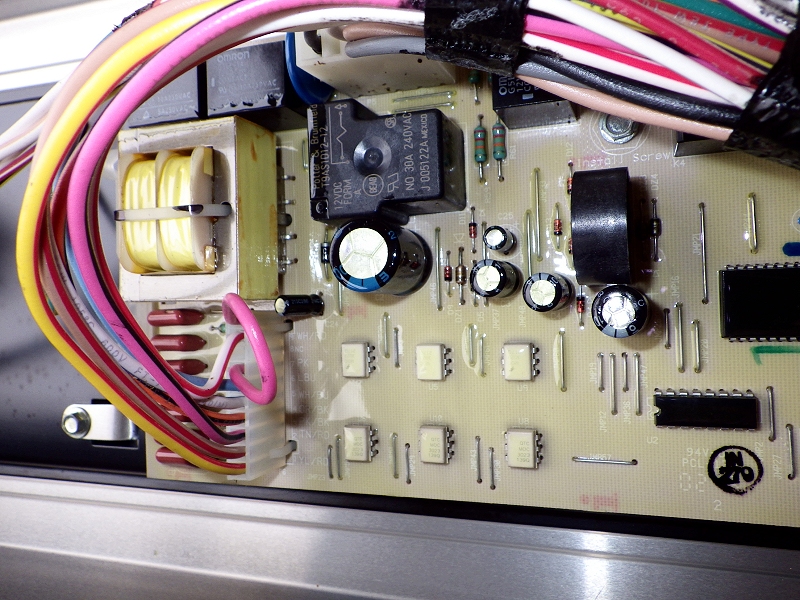
Relay pin-out bottom view, pin 3 output to diverter valve 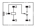
| ||
|
Post# 714956 , Reply# 26 11/12/2013 at 20:29 (3,815 days old) by DADoES (TX,�U.S. of A.) |
||
|
| ||
|
Post# 715051 , Reply# 27 11/13/2013 at 10:06 (3,815 days old) by kb0nes (Burnsville, MN) |
||
|
Yes the relay should be either on or off. I can't really see a failure mode where it could "leak" though. I'd want to check to make sure that the relay coil wasn't staying energized when it shouldn't be. Something further back on the control board may be the failure.
If indeed the relay is bad it is an easy thing to swap out, Google the part number and you will find them if you need a replacement. This is a similar relay I have replaced on a few furnace boards. | ||
|
Post# 715055 , Reply# 28 11/13/2013 at 10:48 (3,815 days old) by combo52 (50 Year Repair Tech Beltsville,Md) |
||
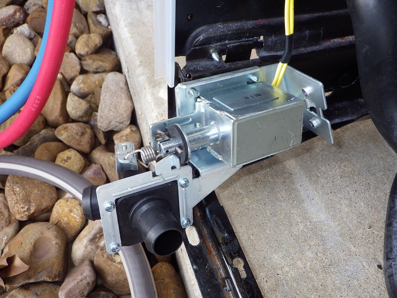
Two-Way Valve Great discussion Guys, these TWVs do have a 120 volt A/C solenoid coil, it is the same valve and coil that was used on the non-electronic Catalyst machines and on the WP=KM Resource-Saver DD Washers.
Foot note for WP & KM 29" Combo restorers, the valve part of these TWVs works perfectly on these combos. | ||
|
Post# 715113 , Reply# 30 11/13/2013 at 15:12 (3,815 days old) by DADoES (TX,�U.S. of A.) |
||
|
| ||
|
Post# 715114 , Reply# 31 11/13/2013 at 15:13 (3,815 days old) by DADoES (TX,�U.S. of A.) |
||
|
| ||
| Forum Index: | 
| Other Forums: |

|

|

|

|

|

 Comes to the Rescue!