Thread Number: 50753  /  Tag: Vintage Automatic Washers
MAYTAG TWO-BELT TRANSMISSION QUESTION
[Down to Last]

automaticwasher.org's exclusive eBay Watch:
scroll >>> for more items --- [As an eBay Partner, eBay may compensate automaticwasher.org if you make a purchase using any link to eBay on this page]
Post# 730101   1/24/2014 at 10:48 (3,743 days old) by jwpate ()        

HI
I am in the middle of overhauling the transmission on the MAYTAG from 1986. I had hoped to replace the input pinion bearing, which is made of nylon, and its two clutch washers. None of the items are available from MAYTAG so I will have to reuse the originals. My question regards the screw which holds the pinion gear in place. When I took it apart it seemed to be set loosely in place and prevented from changing position by the groove pin. As I am about to build it back up, I just wonder if another member has knowledge of how tight I should take the screw, before placing the pin.

Thanks


Post# 730277 , Reply# 1   1/24/2014 at 20:23 (3,742 days old) by beekeyknee (Columbia, MO)        

beekeyknee's profile picture
Until the screw pushes the pinion down flush with the top of the splines on the shaft.

Post# 730701 , Reply# 2   1/26/2014 at 14:52 (3,740 days old) by DigAPony ()        
None of the items are available from MAYTAG

I think you can find a new pinion gear if you shop around. However, that one appears in good shape and should be okay for reuse provided there are no hairline cracks developing.

Lugs gears can be reused as well if not badly worn but should re-installed in their original positions. Again new would be best and they should be available somewhere, although parts such as these are getting scare lately.

www.automaticwasher.org/cgi-bin/T...


CLICK HERE TO GO TO DigAPony's LINK


Post# 730704 , Reply# 3   1/26/2014 at 15:09 (3,740 days old) by jwpate ()        

Well that question did sort of answer itself when I started building up the transmission. After screwing down the pinion to the shaft, neither of the available pin holes would prevent the screw from backing off a bit. That is the slack I noticed during strip-down and seems normal to me now.

As to locating new pinions and washers, I expect you just haven't been searching for them recently. MAYTAG PARTS ONLINE.COM, PARTS DR., and REPAIR CLINIC all report the same sad news - NO LONGER AVAILABLE.

Thanks though, to digapony. I followed that link to Appliance Jungle and now have the pinion on order.


This post was last edited 01/26/2014 at 18:53
Post# 730710 , Reply# 4   1/26/2014 at 15:22 (3,740 days old) by jwpate ()        

While I certainly do not have the experience (none) to start in on a step-by-step how-to on this washer, I would like to post a few photos along the way in hopes that more experienced eyes may catch my errors before they become real problem issues.

I have the machine completely apart now and have found sources for just about all I believe I shall need. Nothing much is available anywhere I have looked for the transmission. Only the gasket.

In the below photo I have rigged up a threaded rod with appropriate plates to clamp the brake spring, then removed the ring of machine screws, and finally am backing off on the spring pressure and allowing the brake halves to move apart.


Post# 730711 , Reply# 5   1/26/2014 at 15:30 (3,740 days old) by jwpate ()        

Here the parts have been cleaned and I am inspecting the brake friction lining. It is only about 2 MM thick, at the spot I have the ruler on. I am working on finding a manual for this model A112, but without success thus far. So I don't know what the practical limit might be. All the rest of the assembly parts look good to my untrained eye, but I have placed a new brake on order because that friction lining looks too thin.

Everything is original from 1986 and so I haven't bothered to clean up the two bearings. I have new ones.


Post# 730716 , Reply# 6   1/26/2014 at 15:45 (3,740 days old) by jwpate ()        

The old mounting stem on the right looks to be a far higher quality part than the new unit on the left. It must be changed, of course, but the new stem uses a cheap rubber lip seal, unlike that nice original seal, which was spring loaded against the washer and retained by the wire clip. That spring loading would have continuously kept pressure on the rubber and helped it retain a firm seat around the shaft.

A fellow member of this forum has suggested that I use both the new stem seal and a new specimen of the original style seal fitted underneath it. I would have never thought of doing that, but most certainly will give it a go. First I shall clean the grease from inside both the seals and replace it with something else, in order that I don't go mixing grease types.


Post# 730718 , Reply# 7   1/26/2014 at 15:52 (3,740 days old) by jwpate ()        

I went through the transmission in order to satisfy myself that there were no obvious problems with any of the gears. They all look good. I can see slight wear on both the pinions, and would like to use new clutch washers - but we have already discussed that.

So it will be just a cleaning effort and new oil. I do want to fit a new central shaft seal though.


Post# 730720 , Reply# 8   1/26/2014 at 16:01 (3,740 days old) by jwpate ()        

Starting in 1986 when I bought this washer, MAYTAG switched from using an O ring located inside the transmission case (up near the nylon pinion in previous image) to a lip seal fitted right at the end of the lower case leg. The seal has a steel sleeve inside that plastic cover, and by means of a special tool it can be pulled off and changed, without opening the transmission or even removing it from the washer.

The new seal comes with a neat plastic protector for installing it. Here I just tapped it in with a hammer.


Post# 730721 , Reply# 9   1/26/2014 at 16:13 (3,740 days old) by jwpate ()        

And now for something really ugly! This is the lip of the outer tub. At this location was one of the two clamps for that stainless V-band which secures the tub seal. I start wondering about how to deal with this. Sure cannot just order a new outer tub.

How bout brazing, or silver solder, or auto-body lead? How bout some epoxy product, like JB Weld.


Post# 730722 , Reply# 10   1/26/2014 at 16:17 (3,740 days old) by jwpate ()        

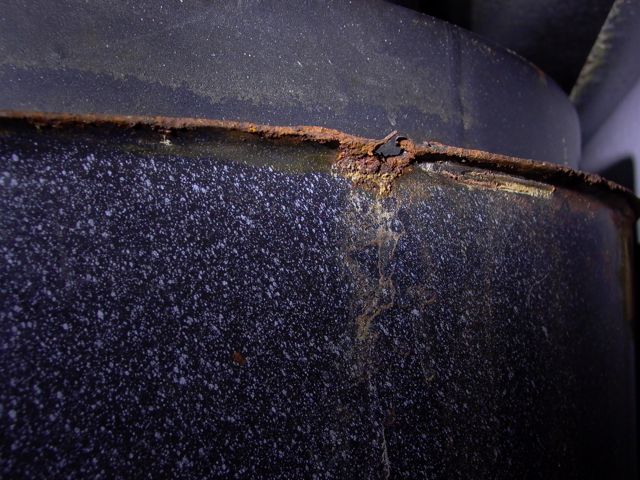
Whatever is to be done, the first step must be to clean it back till reaching good sound metal. And, this step takes me past all the aforementioned ideas.

It will have to be a butt welded patch of steel.


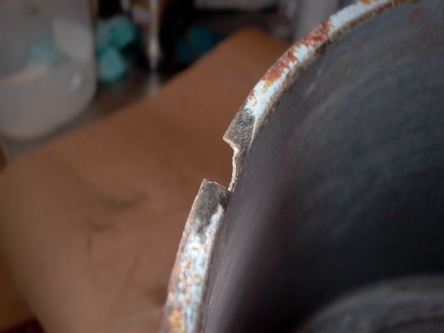
Post# 730723 , Reply# 11   1/26/2014 at 16:20 (3,740 days old) by jwpate ()        

So, start by hammering out a patch to the contours needed, place it in position and scribe the edge pattern onto the tub, then cut out to match.

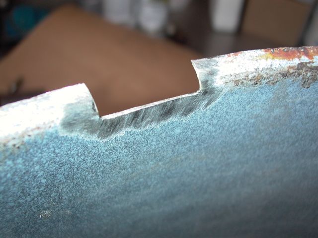
Post# 730725 , Reply# 12   1/26/2014 at 16:22 (3,740 days old) by jwpate ()        

Weld it in - grind it smooth- and move on to the next issue.

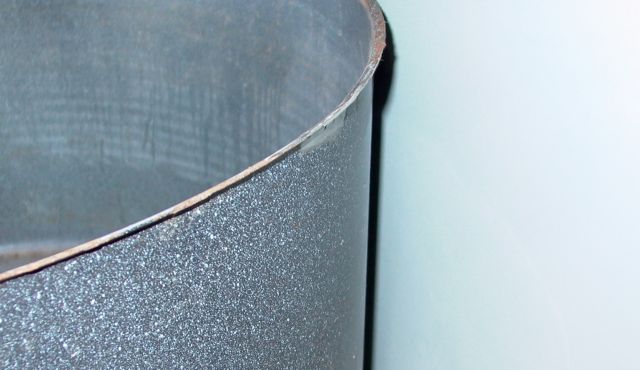
Post# 730726 , Reply# 13   1/26/2014 at 16:27 (3,740 days old) by jwpate ()        

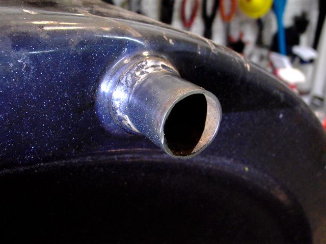
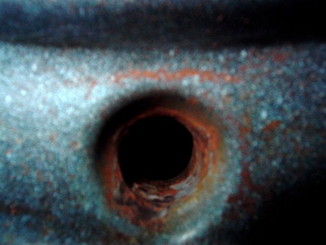
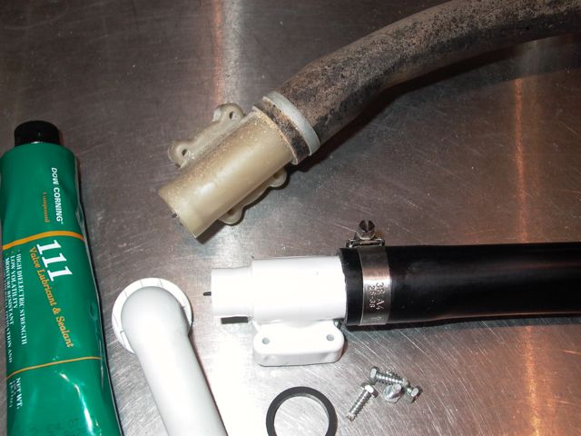
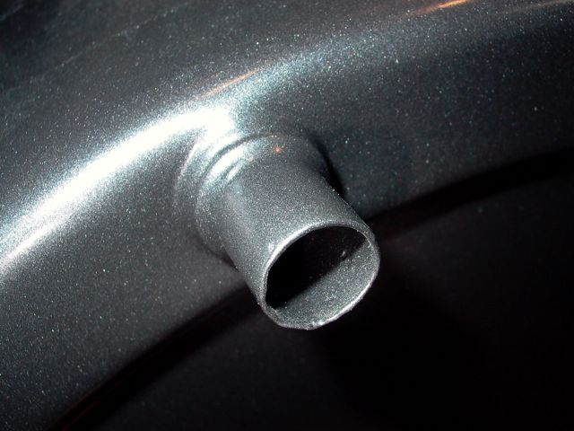
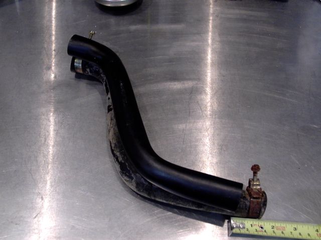
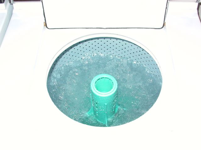
And this will do. Here is the drain pipe of the outer tub, looking worse for wear. There seems enough length remaining for attaching a hose, but how sound is this pipe???

Post# 730729 , Reply# 14   1/26/2014 at 16:32 (3,740 days old) by jwpate ()        

Well, it actually looks better after the useless end is cut away. But I cannot just clean it up and expect it to be good-to-go. It will have to be really completely cleaned of rust and coated inside and out with a surface will protect it from further oxidation. What to do?

Post# 730730 , Reply# 15   1/26/2014 at 16:37 (3,740 days old) by jwpate ()        

This is what it looks like from inside the tub.

I have come around to thinking that the only acceptable thing to do is bead blast the entire thing, inside and out. And I mean the entire tub. That old finish was a baked on enamel by the looks of it, and I am thinking that it will soon have a baked on power coat. Just cannot think of any other way to make it last.

Anyone else been faced with this and found a better way?


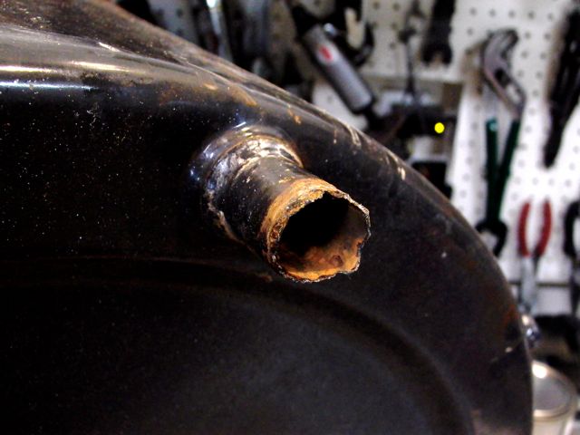
Post# 730744 , Reply# 16   1/26/2014 at 17:36 (3,740 days old) by washman (o)        
Good work

Your work with metal is most impressive.

Post# 730800 , Reply# 17   1/26/2014 at 21:06 (3,740 days old) by DigAPony ()        

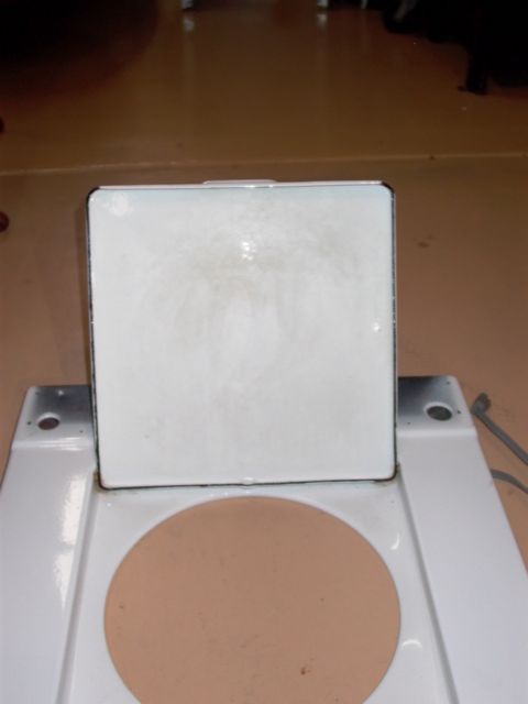
The tub is porcelain enamel finish.

I'd suggest using POR-15 on the rough spots and use as is.

If you decide to strip it and re-coat there are places that can do a porcelain enamel finish for not much more that powder coating.


Post# 731603 , Reply# 18   1/29/2014 at 17:48 (3,737 days old) by jwpate ()        

Thanks DigAPony, but I cannot locate anywhere in this metropolis a firm offering porcelain enamel refinishing. So I am going ahead with powder coating. We don't expect to remove the existing porcelain where it is sound, but only etch is with the bead blasting then coat over it. The rust can be really cleaned up that way, including the drain pipe. I thought about other options, including reaming out the drain pipe and soldering in a thin stainless sleeve. The heat would be too much though, so I am going with powder coat.

In the time waiting for the tub to be completed, I can move on with other issues. Here the cabinet is outside with fresh paint. I cleaned the rust areas and coated with POR15. After that was dry it got a coat of Hammerite.


Post# 731610 , Reply# 19   1/29/2014 at 18:07 (3,737 days old) by jwpate ()        

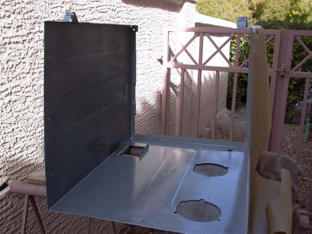
And while taking the top cover apart, I came upon this bonus. There can be seen a wiring diagram for my model, where it has been taped in for all these years.


Post# 731612 , Reply# 20   1/29/2014 at 18:15 (3,737 days old) by jwpate ()        

This water valve also came out today, getting the cabinet ready for attention. I hadn't thought much about the valve before now, as it seemed to still be working OK. It looks like its best years are behind it though, doesn't it. That small hose clamp is too rusted up to come off, so I just cut the hose. I have already decided to replace all the rubber hose sections as a matter of course.

Can't get that design hose clamp these days though. They weren't that great anyway, and more on hose clamps later.


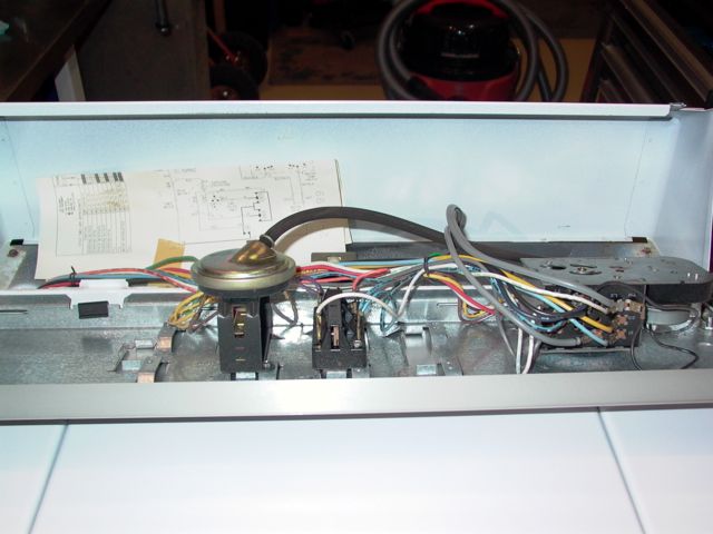
Post# 731613 , Reply# 21   1/29/2014 at 18:20 (3,737 days old) by jwpate ()        

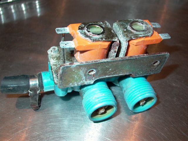
Took the inlet valve apart to gain a better understand of how it works. It is those rubber discs which eventually will perish enough to allow water leaks, and I expect serious ones.


Post# 731617 , Reply# 22   1/29/2014 at 18:35 (3,737 days old) by jwpate ()        

And since I will be ordering a replacement inlet valve, I remembered another question which I have not yet answered.

Anyone on this forum will probably immediately recognize these three amigos. They are the outer tub mounting bolts, with what the supplier refer to as rubber sealing washers. My plan was to cut some replacement washers - but from what material? They may call them rubber if they wish to, but they seem more like polyurethane to me. Anyone know for sure?

I suppose the safest and easiest thing to do would be just replace the three bolts with new ones, as they come with the washers attached. I haven't located a source for the two longer bolts, while the short one is available from many sources. So I shall just order three of the short ones. Actually, I haven't worked out why they used long ones on the back tub braces anyway. There is always a reason, but I could only guess on this one.


Post# 731621 , Reply# 23   1/29/2014 at 19:01 (3,737 days old) by jwpate ()        

Back to the subject of hose clamps. I did order a full set of hose clamps for the washer, for they all are rusty. The order was with MAYTAG, and that item on the left is what Whirlpool now ships out as "factory certified parts". In its favor is the fact that it is made of stainless, but I would only use in a pinch and short term. That type clamp is second rate because of the effect those slots will have on the rubber hoses. The hoses are not inexpensive, and we want long life from. The original clamps had a smooth surface against the rubber, and we can find that too in worm style clamps. The clamp on the right is first rate, and the style I shall be using.


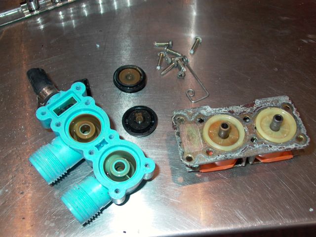
Post# 731622 , Reply# 24   1/29/2014 at 19:04 (3,737 days old) by jwpate ()        

And the mail has just been brought in. With is is this like new factory workshop manual for the exact model I am working on. Mine is a 112.

This is great news, and was on eBay last week.


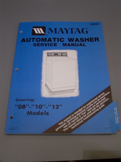
Post# 731636 , Reply# 25   1/29/2014 at 19:52 (3,737 days old) by beekeyknee (Columbia, MO)        

beekeyknee's profile picture
Hi James,

Unless the rubber is damaged on the underneath side of those bolts you may reuse them again. I've always reused them before and never had any trouble. Have you tried PB Blaster on your rusted clamps. That usually brings them back, but the new one you show on the right looks nice.

Brian


Post# 731658 , Reply# 26   1/29/2014 at 21:30 (3,737 days old) by jwpate ()        

Thanks for the response Brian. And I have not forgotten your recommendation to check eBay for a service manual. This one has been fun for me looking through, and I did already hit upon a slight surprise in the section on replacing the mounting stem and boot seal. The service manual instructs us to lubricate the carbon ring with thin film of transmission oil before screwing on the mounting stem. Note: the manual uses the term "carbon seal".

Now, when I look at the instruction sheet which came with the new Whirlpool replacement stem and seal, the only "instruction" given is to wipe the face on the bootseal and TEFLON ring on mounting stem with a clean cloth, with the warning "lubrication will reduce the life of the seal face".

I remember this contradiction too, from reading your excellent step-by-step thread. It does seem likely to me, that the carbon seal which MAYTAG once used has been replace by teflon in the Whirlpool version. I am going to put them in clean and dry.


Post# 731661 , Reply# 27   1/29/2014 at 21:56 (3,737 days old) by DigAPony ()        
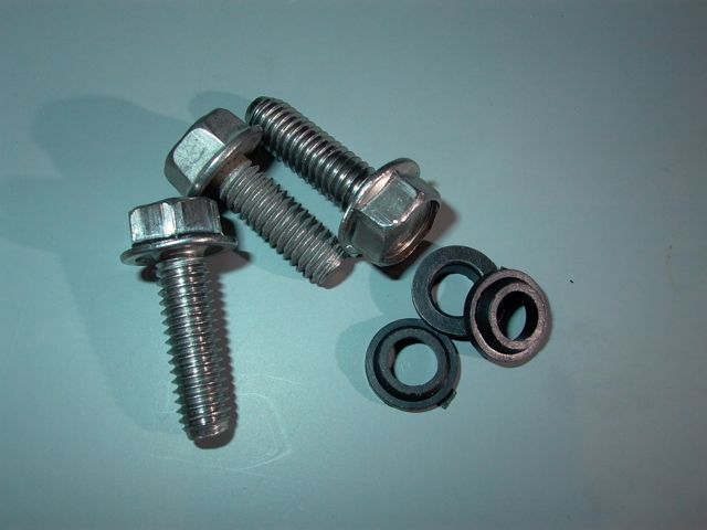
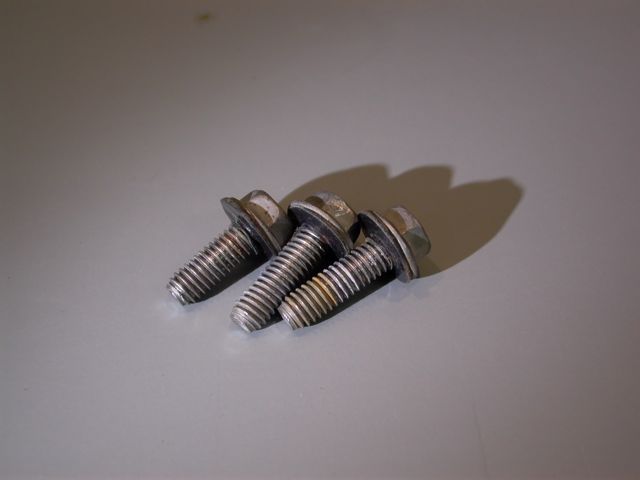
bolts you may reuse them again.

I'd put some RTV sealant on the bolt gaskets for a little extra insurance.


Post# 731809 , Reply# 28   1/30/2014 at 14:32 (3,736 days old) by redcarpetdrew (Fairfield, CA)        
Wow.

redcarpetdrew's profile picture
I've been following this thread with great interest and all I can say is WOW! You are doing one heck of a job restoring this little one. I admit I came in on this later than most. I work at a Maytag service center in Reno. I do have access to a ton of service manuals and part break downs. What do you need, if anything? Might I ask what part of Nevada are you in? It's really good to know I'm not the only AW'er here now!

If this helps, this is a thread I did a while back with part numbers, etc...

Hope to hear from you!

RCD


CLICK HERE TO GO TO redcarpetdrew's LINK


Post# 731828 , Reply# 29   1/30/2014 at 15:41 (3,736 days old) by jwpate ()        

Thanks for the encouragement Drew. Your reputation has preceded the above posting, for I already am aware of redcarpetdrew and your contributions to this forum. I hope you will call me out and set me straight whenever I seem to be heading off in wrong directions. I am down in the Las Vegas valley Drew, and this is my first attempt at a Maytag overhaul. Brian has been advising me and so naturally, I have already looked through one of your threads. Will be sure to read this one too, ASAP.

Well, they seemed to use a different size and length sheet metal screw for every requirement. I thought of trying to source some replacements in stainless, but don't believe I would find all the shapes and sizes. So I will have a go at the originals, and none of them are missing.


Post# 731829 , Reply# 30   1/30/2014 at 15:52 (3,736 days old) by redcarpetdrew (Fairfield, CA)        

redcarpetdrew's profile picture
For a first attempt, you are out shining some techs I've known. The only thing I'm not certain about is replacing the lower o ring seal on the lower transmission shaft. I've not seen anyone use the newer lip seal in place of the o ring as I thought the lower shafts were slightly different between the o ring using helical and the lip seal using orbital. I by no means claim to be the authority, since when I do it ends up spanking me, and will love to see the results of experimentation.

That is the best example of saving a rusted outer tub ever! You, my friend, have the touch. Keep going!

RCD


Post# 731830 , Reply# 31   1/30/2014 at 16:00 (3,736 days old) by jwpate ()        

With the tub out for coating, I am just about dead in the water anyway to I went after the hardware bits today. I know I will not have done them all, but this is the lions share. They appear to have been zinc plated in their first life, and that has given about all the protection it is able to. Most are rusted, but not badly pitted.

So I spent the morning bead blasting these items and then re-plating them but this time in nickel.

The adjusting bolts also got new hard rubber feet.


Post# 731834 , Reply# 32   1/30/2014 at 16:25 (3,736 days old) by jwpate ()        

I just wasn't very clear Drew, in that posting about the lip seal. I am not using it in place of the O-ring, for my transmission never had the O-ring. I was simply replacing the lip seal which came on the washer from new.

The special tool, seen below, is really a fine thread tap, which cuts through the covering and into the steel sleeve which is inside the lip seal. By first removing the brake assembly it is thus possible to change this type seal without pulling the transmission out. It is removed by getting a bite on the seal sleeve and then using the bolt of the tool against the helix end to pull the seal out around the central shaft. It is replaced by using that red protector in the earlier photo and driving it home using the pulley on the helix threads.


Post# 731836 , Reply# 33   1/30/2014 at 16:37 (3,736 days old) by jwpate ()        

And the UPS truck just dropped off a new transmission nylon pinion gear. Thanks again DigAPony for that lead to appliancejungle. I have the gasket for the transmission too, but will hold off closing it up because it does seem that the two new clutch washers have been located, thanks to fellow forum member Brian.

Post# 731841 , Reply# 34   1/30/2014 at 17:45 (3,736 days old) by redcarpetdrew (Fairfield, CA)        
There we go.

redcarpetdrew's profile picture
As I said, not the all seeing!

Forgot that during a short period when they were phasing the orbital in, both styles got the lip seal. Good show! Done that lip seal surgery a few times. Not bad to do but sometimes is annoying as it doesn't last (very seldom, tho...)

I am just loving the picture I have in my head of what she's going to look like when you're done! Can't wait for the inaugural wash (with accompanying hi def video of course!). Almost worth the roadie to Vegas to watch her rebirth.

RCD


Post# 731871 , Reply# 35   1/30/2014 at 19:38 (3,736 days old) by combo52 (50 Year Repair Tech Beltsville,Md)        
Cool Rebuilding Job

combo52's profile picture
I know you are having fun with it. A Few Thoughts that might help.

Powder coating the outer-tub should be very sufficient, I have never found a company that will actually re-coat porcelain on metal as thin as an outer tub. Most companies want to sandblast off the old coating first and doing so on thin metal can literally leave holes.

As a technician for over 40 years I have never seen a nylon pinion gear or the thrust washers wear to the point that they caused any problem with the operation of the washer, and I suspect that if you wanted to disassemble your rebuilt MT transmission after about two years of use you will see the same scoring and very slight wear on the nylon pinion gear that the transmission you are rebuilding now shows.

The brake lining of the brake assembly looks completely normal as it is for all practical purposes as good as new.

The orignal MT center pull hose clamps are a very good type of clamp, and you are correct that the typical worm gear clamps are not a great hose clamp, overall the best type of clamp you can have are the flat spring clamps, but unfortunately you must have the exact size for the job, so the SS band clamps you are using are as good as the orignal MT clamps and should work great for this purpose.

John L.


Post# 731880 , Reply# 36   1/30/2014 at 20:22 (3,736 days old) by DigAPony ()        
re-plating them but this time in nickel.

I was going to suggest checking Craigslist, late model Dependable Care Maytag washers are good source for major and miscellaneous donor parts that can interchange with MT washers going back to the '60's.

But since you've already re-plated the hardware in nickle, um, never mind...
This resto is obviously on whole other level.


Post# 731944 , Reply# 37   1/31/2014 at 03:46 (3,736 days old) by jetcone (Schenectady-Home of Calrods,Monitor Tops,Toroid Transformers)        
A very impressive

jetcone's profile picture

restoration and I'm even more impressed if I understand correctly that you are the original owner of the machine? 

Replating in nickel - boy do I  envy that! But nickel can be toxic if not handled properly how do you do it?


Keep a goin!!


Post# 732007 , Reply# 38   1/31/2014 at 10:23 (3,736 days old) by JWPATE ()        

Well thank each of you for the encouragement. Believe me fellows it is appreciated, as is the advice and information.

Yes, I bought this washer new from the MAYTAG dealer in New Orleans. It would have been '86 or '87. We have been in Southern Nevada now for the past 15 years. Here, just about all of us use salt-brime water softeners, for the water is seriously hard without it. It does have a toll on appliances however. I am on my third water heater now, and I do believe the greater part of my sheet metal rust is related to that.

Several weeks back, while a load was washing, I got a report that "we need a new washer, that old one is screeching and burning up!" The fault turned out to be a heavy fabric item, which had found its way into the gap between the inner tub top and the outer tub cover just as the spin cycle was starting - and jammed things up. The smell was burning rubber from the drive belt of course. After clearing the cause, the machine seemed to return to normal operation, but there were other reports that it also hadn't been getting enough water out of spin loads.

So I went into this with the expectation that a set of new belts would be in order. After taking off the front cover though, and looking in there at the dust, rust and neglect, a sense of guilt began to take over. Almost thirty years now of faithful service, and this sad view of utter neglect seemed to point a finger directly at me with the words shame, shame on you. This is why it has now evolved into a general overhaul. My attitude is that anything made of rubber or plastic, whether leaking or not, has already performed its duty and deserves an honorable retirement. As john points, this will undoubtably lead to some over-kill, such as the brake assembly, clutch washers, and pinion gear. But in those cases I shall just save the old items as good used parts for the future. And I plan to keep this MAYTAG A112 going in full service for as long as I am able.

Going in, it was necessary to understand the helix drive operation, and members of this forum made that possible. Now I even have a service manual. And, the reading has given me a great respect for the clever design as well as the high build quality of the old MAYTAG washers.

On re-plating the small hardware items, that is fairly routine for me as a spill-over from my old car interest. It is just faster and easier to do it yourself on plating parts small enough to fit into my five gal. plating buckets. I would have done them in zinc if close tolerance was an issue, but with parts such as this I prefer nickel for it has performed better for me protecting steel items in high humidity conditions.

No, neither nickel nor zinc are especially dangerous to work with. Cadmium most certainly is though, and for all practical purposes it is also illegal in small operations.

Yes Drew, I have made that drive from Reno to Vegas a few times, and Brother, it's a long and lonesome road!

James


Post# 732009 , Reply# 39   1/31/2014 at 11:10 (3,736 days old) by beekeyknee (Columbia, MO)        

beekeyknee's profile picture
James,

Softened water and water heaters don't mix well. I found out the hard way. Here's what I did. Read the link in the link first. It was quite an ordeal, but all seems well now.

Brian


CLICK HERE TO GO TO beekeyknee's LINK


Post# 732057 , Reply# 40   1/31/2014 at 15:37 (3,735 days old) by JWPATE ()        

I took a quick look Brian, and there is a lot of information there. After the washer fun is over I plan to do a detailed study of your water heater thread.

For now, I did count the threads on a couple of the eye bolts. They averaged 19 threads, and so I have marked these for use as a starting point when things go back together. There are four in the photo, because I did order one new bolt to replace a pitted one. Actually they all cleaned up ok for reuse, and I did nickel plate the new one right along with the other three. That is the new bolt on the right side. The interesting thing is that they are different lengths. Originally, there would have been two of the short ones and one longer one (the new one is also longer). I doubt there is anything to it more than different bolt lots at the factory. Interesting though.


Post# 732058 , Reply# 41   1/31/2014 at 15:42 (3,735 days old) by JWPATE ()        

The washer lid was also showing rust spots along the sheet metal edge on the bottom and sides. There was already a black section in the corners, and I just continued it along the bottom and sides. It is only POR15 paint, but should last a good while, and this location is easy to keep a watch on.


Post# 732061 , Reply# 42   1/31/2014 at 15:48 (3,735 days old) by JWPATE ()        

Here at the control panel I didn't do more than clean the electrical contacts. I wondered whether those gear wheels inside the timer switch might benefit from lubrication.......but decided to leave well enough alone and simply blew out the dust.

Very interesting though, looking at the backing panel with all the provisions for additional switches and push buttons. Lucky for me, this machine is the simple model.


Post# 732063 , Reply# 43   1/31/2014 at 15:56 (3,735 days old) by JWPATE ()        

The old order and the new. This is the anti-syphon valve, which positions just before used wash water leaves the machine for the drain hose. I suspect this is included to satisfy some federal reg.
Anyway, the hose clamp is interesting, and one scratches the head while wondering how did they get the thing on there? I have some similar pinch clamps they were all either too large or too small, so we go with the worm clamp as planned.

Used Dow Corning 111 inside the hose and on the sealing washer.


Post# 732065 , Reply# 44   1/31/2014 at 16:00 (3,735 days old) by JWPATE ()        

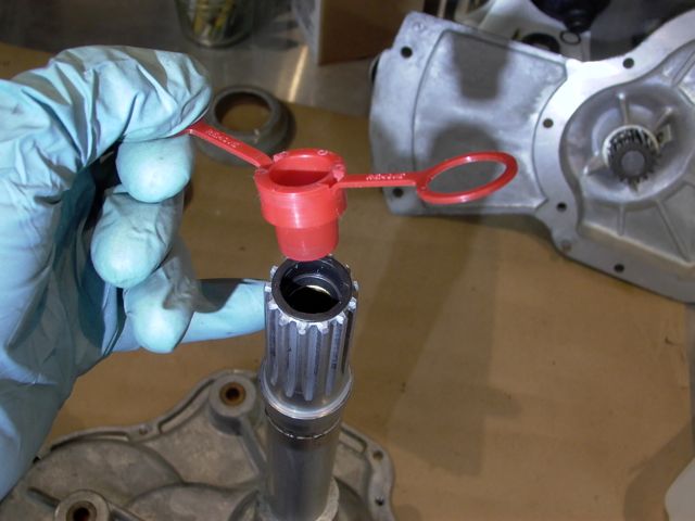
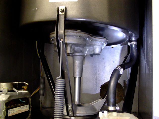
Naturally, I waited until the top was on the cabinet before fitting the drain stem and anti-syphon valve. That way it was as awkward as I could make it.

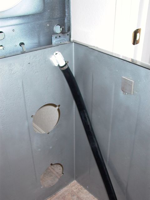
Post# 732131 , Reply# 45   1/31/2014 at 20:19 (3,735 days old) by combo52 (50 Year Repair Tech Beltsville,Md)        
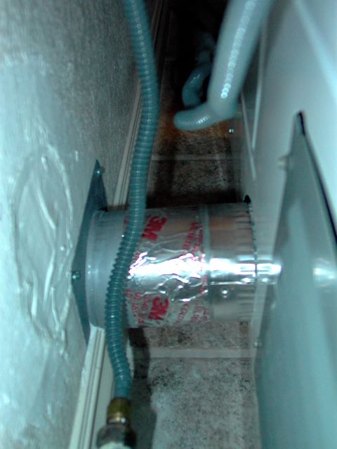
Anti-Siphon Device in The Drain Line

combo52's profile picture
This was not required by the Feds or even plumbing codes, but rather allowed the washer to be used with a floor drain, It also eliminated many other service calls such as an overflowing washer when the end of the drain hose becomes submersed in a sink that is backing up and the washer starts agitating for rinse and sucks all the backed up water in sink back into the washer and causes the washer to overflow. This type of event often cost the appliance maker money on warranty calls. MT did eliminate this feature later on.

Post# 732146 , Reply# 46   1/31/2014 at 21:36 (3,735 days old) by JWPATE ()        

That is very interesting to learn the true reasons for that anti-syphon device. It is simple enough that probably it didn't often become the source itself of leaks.

Post# 732215 , Reply# 47   2/1/2014 at 10:25 (3,735 days old) by beekeyknee (Columbia, MO)        

beekeyknee's profile picture
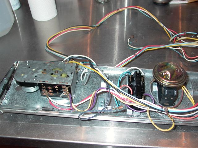
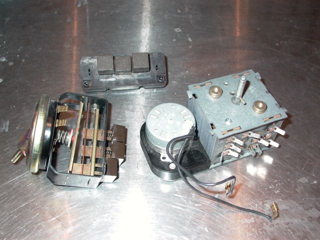
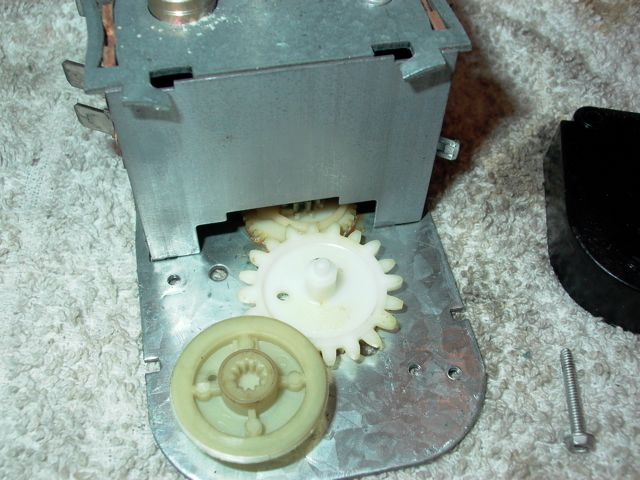
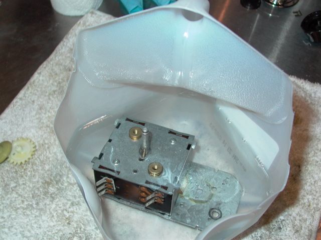
It looks like you have a late model Mallory timer in that machine. I usually see Kingston timers in that age of machine, but it can vary. The timer can be cleaned and lubricated if you want. With neoprene gloves on, I submerge the timer in kerosene and operate it while submerged. Then I let it dry overnight in a ventilated area and after it's dry I spray the timer down with Tri-flow spray or silicone spray, shake out the excess and let set for awhile. The escapement on your timer is very simple compared to the early model ones.

You might want to wait until you get the rest of your rebuild done before messing with the timer, if you choose to at all. That timer can be pulled out of there any time to be worked on. And don't forget to remove the motor before maintenance.


CLICK HERE TO GO TO beekeyknee's LINK


Post# 732233 , Reply# 48   2/1/2014 at 13:22 (3,734 days old) by JWPATE ()        

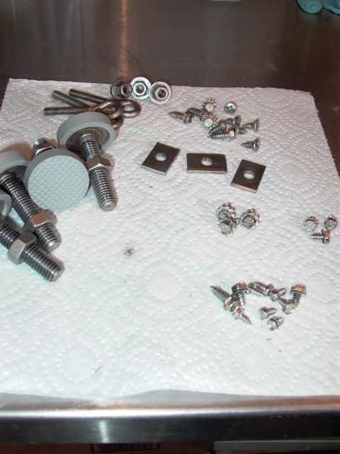
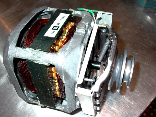
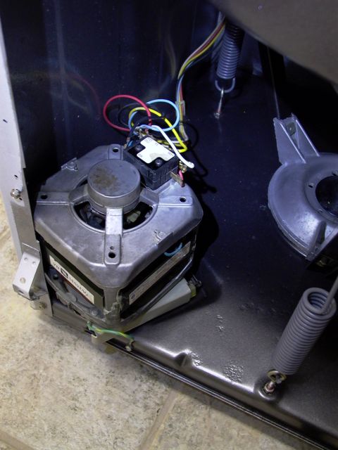
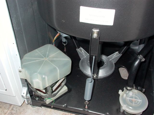
Yes, that is quite interesting, and I just may have a go at that timer in the next few days. Otherwise running out of things to do while waiting for the tub.

For this morning, I turned my attention to the main washer motor and its spring plates.


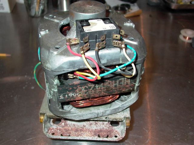
Post# 732234 , Reply# 49   2/1/2014 at 13:25 (3,734 days old) by JWPATE ()        

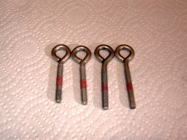
Not a pretty sight is it, and the underside looks even worse. Still I was wondering about reusing those plates, after cleaning them up and re-plating in zinc.

Post# 732236 , Reply# 50   2/1/2014 at 13:30 (3,734 days old) by JWPATE ()        

But I most certainly wanted to put in new springs, and at the time (two weeks ago) the springs were not available from Repair Clinic. I have many more sources for parts now, thanks to this forum, but I did order a kit which includes the springs. So I plan to use it.


Post# 732238 , Reply# 51   2/1/2014 at 13:41 (3,734 days old) by JWPATE ()        

First step was to take off the drive pulleys, and that went without a problem. But the pulley which drives the transmission (larger one) was seriously coated with rubber. That burning rubber smell which started this exercise was evident here, where the rubber was vulcanized to the steel. I was getting nowhere with wire brushes, steel wool and acetone. Eventually I got it off with an x-acto knife followed by bead blasting.

I expect the pro's carry a few of these things around with them. I would!


Post# 732241 , Reply# 52   2/1/2014 at 13:50 (3,734 days old) by JWPATE ()        

The motor mount kit, which MAYTAG offers these days, comes with square sliders instead of the original style round rollers. Now, actually the round ones didn't really roll either. They too slid along rather than turning on their mounting shafts. Still, after all these years the round wheels look good as new, and are the same dimensions as seen on the stacked-up specimen. And, while it seems to me that the round sliders are less likely to ever bind up, they are coming up on thirty years old. So, and on good advice from this forum I have fitted the new square sliders.


This post was last edited 02/01/2014 at 14:53
Post# 732244 , Reply# 53   2/1/2014 at 13:57 (3,734 days old) by JWPATE ()        

The kit comes with a small tube of what MAYTAG labels as POLY-LUBE GREASE, and that tube is just about the right amount to lube the wheels and slide surfaces. I don't have any more of it though, and just may need to re-lube those slides one day. So I also tossed the grease tube and have used the MOLYKOTE from that larger tube in its place.

Notice the springs. The new ones on the right side are longer than the originals with slightly thicker wire size.


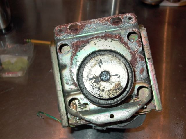
Post# 732245 , Reply# 54   2/1/2014 at 14:01 (3,734 days old) by JWPATE ()        

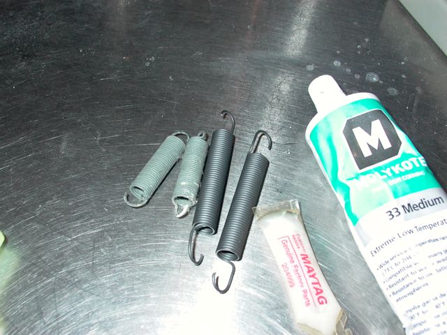
I did conduct a crude testing of the springs, and found that a one-inch extension required just about two pounds in both the old and the new. The new required just slightly more poundage I thought, but likely to have been within the margin of error.


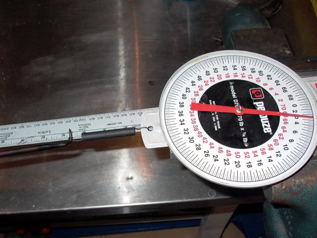
Post# 732250 , Reply# 55   2/1/2014 at 14:08 (3,734 days old) by JWPATE ()        

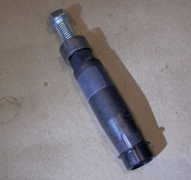
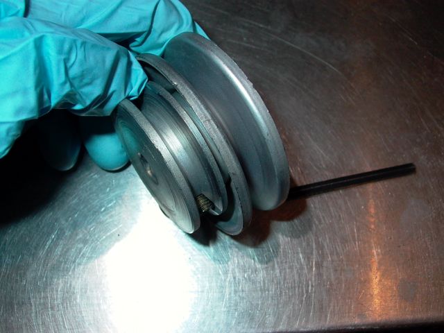
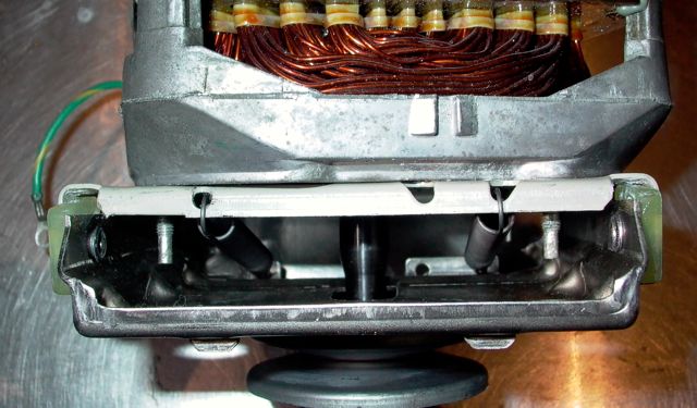
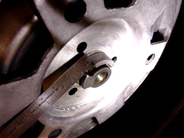
When refitting the pulley to motor shaft notice that the shaft is NOT flush with the pulley face. The service manual calls for a 1/32 inch recess. Here I just peered down the setscrew hole and lined up with the old tightening marks on the shaft flat.


Post# 732257 , Reply# 56   2/1/2014 at 14:14 (3,734 days old) by JWPATE ()        

And there we have it. I of course thought about what would be appropriate to refurbish the motor itself. New bearings for example. But, since they are not offered as spare parts, it would be a very time consuming effort, requiring first getting out the old bearings then finding replacements which are not made in China. I decided to leave well enough alone.


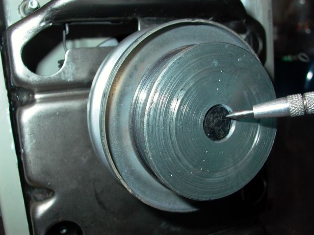
Post# 732259 , Reply# 57   2/1/2014 at 14:16 (3,734 days old) by redcarpetdrew (Fairfield, CA)        

redcarpetdrew's profile picture
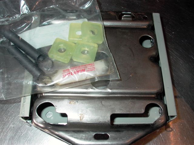
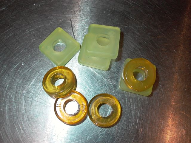
I would use the square 'rollers' on the carriage. The round ones will eventually break/fall apart just due to age. The new ones will work just fine if not a little better. Just trying to save you a possible headache later down the road...

Otherwise, just keep on going the way you are. You're doing awesome!

RCD


Post# 732263 , Reply# 58   2/1/2014 at 14:20 (3,734 days old) by JWPATE ()        

One other change has been thrust upon us. The old hard rubber drain hose with its molded top curve is no longer offered.

The new drain hose is this corrugated affair, which seems to be plastic with rubber ends. Looks like it will be OK, but I do miss the molded top curve. Here I have used wire ties to form the needed curve.


Post# 732267 , Reply# 59   2/1/2014 at 14:24 (3,734 days old) by JWPATE ()        

The wire ties form a sufficient curve to fit it in there well enough. But I do wonder if there is somewhere available some sort of double-ring plastic affair to make a better job of it.


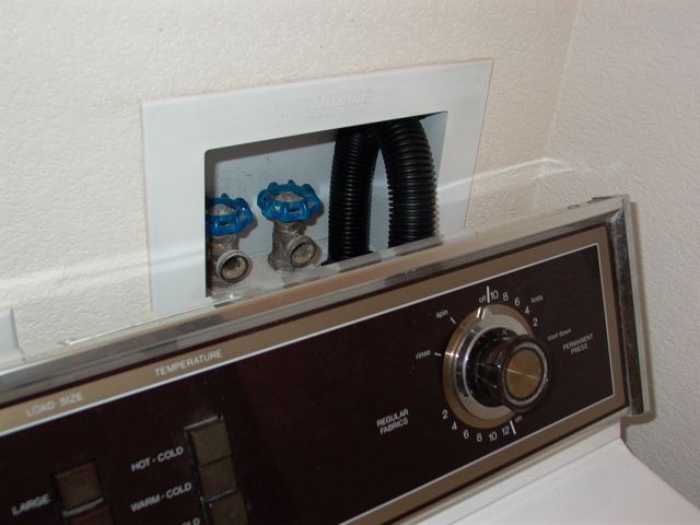
Post# 732270 , Reply# 60   2/1/2014 at 14:48 (3,734 days old) by JWPATE ()        

Thanks for the advice Drew. Get with it James - and don't ask for expert advice unless you are prepared to heed it.

Now the square sliders are well lubed and in place. The old round sliders are in the trash, and all is back as it should be.

Thanks again!


Post# 732357 , Reply# 61   2/1/2014 at 19:38 (3,734 days old) by norgeway (mocksville n c )        
Its great to see!

Someone do something RIGHT! You should be able to use it another 30 years! My Kenmore is 31 this year and I dread the thoughts of something happening to it, i certainly would never tackle what you did!

Post# 732390 , Reply# 62   2/1/2014 at 21:39 (3,734 days old) by JWPATE ()        

Thanks norgeway - and if I do manage to get it right, it will thanks to the experts on this forum.

One more question though, and I bet someone knows the answer!

In the image below, we are looking in at the washer motor carriage, which was completed today. There are two belt-tension springs there, one on each side. But notice that provision exists also for another spring. We could set this carriage up with two springs on one side, or one each side as I have done it, or then again we could use three springs.

I of course, just set it up the way I found it.

But what is the real story on that extra set of holes. I imagined that they most likely were used to provide increased belt tension on models with larger capacity tubs???


Post# 732420 , Reply# 63   2/2/2014 at 04:39 (3,734 days old) by redcarpetdrew (Fairfield, CA)        

redcarpetdrew's profile picture
Sometimes, you'll see a third spring. Usually, the way you have it is just fine.

RCD


Post# 732495 , Reply# 64   2/2/2014 at 15:15 (3,733 days old) by JWPATE ()        

Thanks Drew, I will not worry further on that point.

Just about caught up now, and so decided to take a closer look today at the control panel items. After carefully drawing out a diagram, I realized that actually most of the contacts are labeled and most of the wire ends also are numbered for reference. Better safe than sorry, but now I do have a wiring diagram so the drawing will just make it easy.

My model A112 has but three switching items in the control panel. Water level, water temp, and the timer.


Post# 732496 , Reply# 65   2/2/2014 at 15:27 (3,733 days old) by JWPATE ()        

We shall begin with the water temp switch. From having earlier been inside the inlet water valve, we can just about guess how this functions. There are no partial settings on the solenoid operated hot and cold inlet valves. They are either open or closed, so we know before starting that this three position switch will have the hot solenoid open on the hot button, the cold solenoid on that button, and both open in the mid position.

What I don't know is how exactly this switch accomplishes that job. So we shall have a look inside. First take note that the push buttons are not centered on those actuating shafts, and the long side is up in this view - away from the mounting-hole side.


Post# 732497 , Reply# 66   2/2/2014 at 15:33 (3,733 days old) by JWPATE ()        

These switches are easily available but the buttons alone are not (once they were). So we need to be careful, and hand pressure is all that is needed to persuade them off the shafts in one piece.

Then there are four plastic jaws keeping the top in place, of which we see two on the lower side here.


Post# 732499 , Reply# 67   2/2/2014 at 15:42 (3,733 days old) by JWPATE ()        

I was very careful taking the top cover off, in case there were little springs just waiting to dance across the room. Can be more expeditions if there is ever a next time, for this switch has no springs.

What it does have is two contact breaker points, and a pair of fiber sliders that respond to the rounded ends of the button shafts. It is right in line with our expectations, and when the center button is pushed, neither of the points are opened giving us both hot and cold inlet water.


Post# 732500 , Reply# 68   2/2/2014 at 15:47 (3,733 days old) by JWPATE ()        

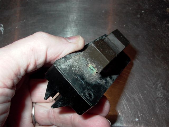
When one of these temp switches begins to give us trouble, I would first wonder about the contact points. So here I give them a few strokes with a flexible point cleaning strip. Just enough to clean them of any oxidation which may have formed there.


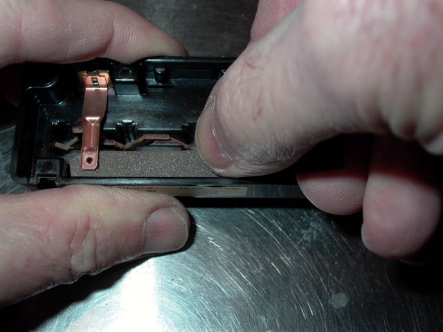
Post# 732501 , Reply# 69   2/2/2014 at 15:52 (3,733 days old) by JWPATE ()        

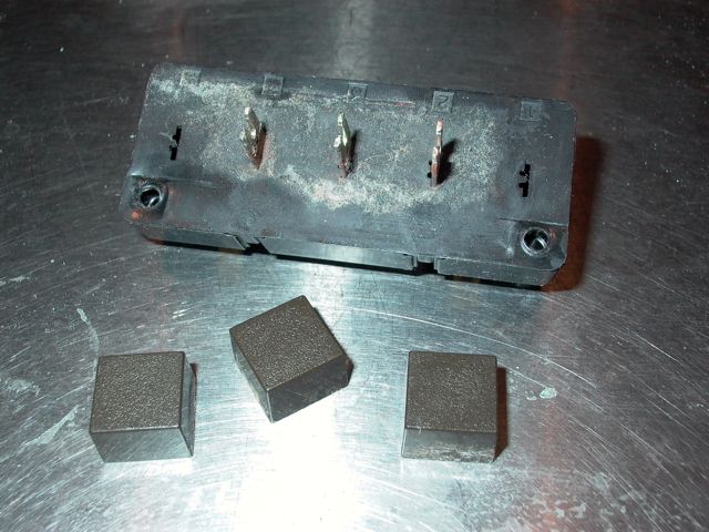
The three actuating shafts were each one corroded at the outside, or button end. Clean them up with fine steel wool and put a film of heavy grease. That Bosch grease is also helpful on the rounded ends which move the fiber sliders.


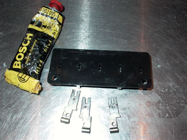
Post# 732502 , Reply# 70   2/2/2014 at 15:55 (3,733 days old) by JWPATE ()        

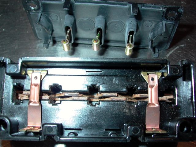
Button it back up and check that my tomfoolery hasn't ruined it. All seems well, the button action is smooth and continuity checks out with no resistance through the contact points.


Post# 732503 , Reply# 71   2/2/2014 at 16:03 (3,733 days old) by JWPATE ()        

Not much we can do to maintain the water level switch. The button system requires no lubrication, and the single set of contact points is safe from me, being inside the diaphragm housing. There was corrosion on the outer metal surface, there under the buttons. I just cleaned it up and painted with POR15.


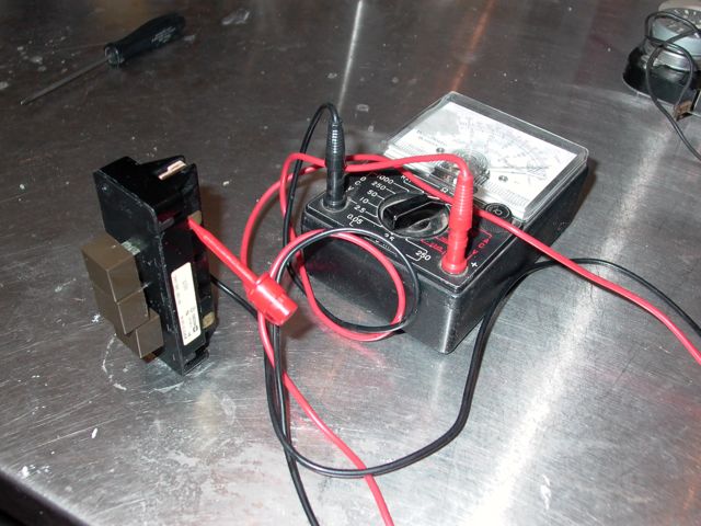
Post# 732506 , Reply# 72   2/2/2014 at 16:08 (3,733 days old) by JWPATE ()        

On to the timer switch. From the link Brian provided a few postings ago, it is understood that this unit is called the Late Mallory model, and much less complicated than earlier timers. Good!

Post# 732510 , Reply# 73   2/2/2014 at 16:15 (3,733 days old) by JWPATE ()        

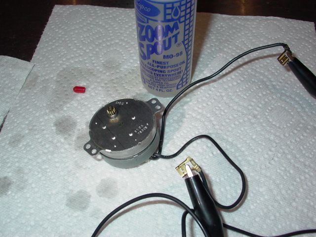
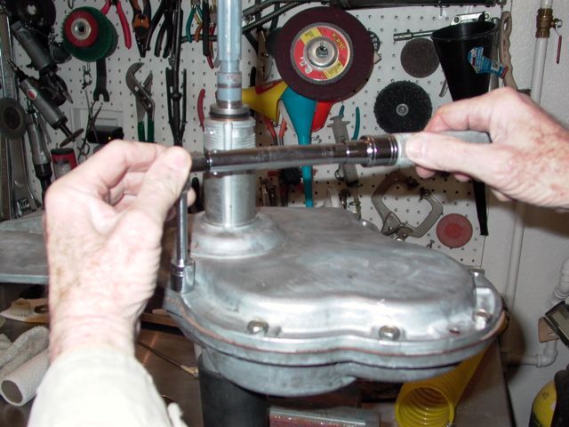
First we take out two fastening screws and remove the timer motor.


Post# 732511 , Reply# 74   2/2/2014 at 16:22 (3,733 days old) by JWPATE ()        

Then remove one more screw and the plastic cover comes off, revealing what I believe is referred to as the escapement gears. That small one, into which the motor pinion was situated, has but two teeth on its bottom side, contacting the next gear only once each revolution. Brian tells us this moves the neat gear in the train along once every minute.

Interesting, but I am here only to clean out dust and old stiff lubricant.


This post was last edited 02/02/2014 at 16:37
Post# 732512 , Reply# 75   2/2/2014 at 16:27 (3,733 days old) by JWPATE ()        

Don't believe it would have occurred to me to try this, had I not read Brian's thread. But here goes, in a high tech kerosene bath and completely submerged to soak a while. Later I used a small brush and removed all the old lubricants. Also pulled out the timer shaft and ran it through all the settings a few times.


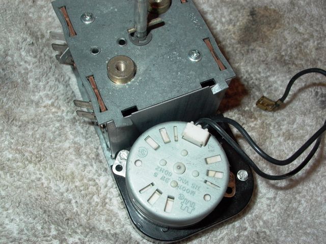
Post# 732513 , Reply# 76   2/2/2014 at 16:31 (3,733 days old) by JWPATE ()        

After it came out, I blew it out well and from every orifice I could find, using compressed air.

And it really does seem clean as a whistle.


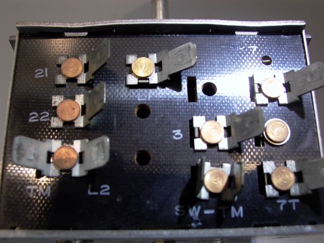
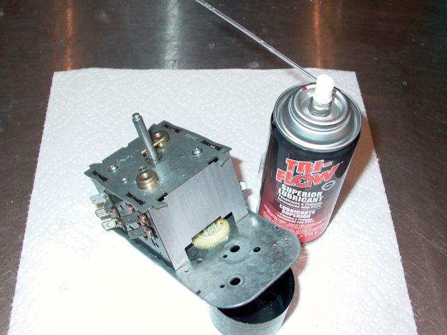
Post# 732515 , Reply# 77   2/2/2014 at 16:35 (3,733 days old) by JWPATE ()        

Will now allow the timer to air out and completely dry from the kerosene.

Tomorrow I will lubricate it again with silicone spray generally, and grease for the gears.


Post# 732673 , Reply# 78   2/3/2014 at 13:03 (3,732 days old) by JWPATE ()        

Yesterday was cleanup day for the timer switch, and today shall be lubrication. That spray can is a product of Sherwin-Williams, the paint people. Its lubricating ingredient is polytetrafluoroethylene. That is a real mouthful, so SW refers to it as P.T.F.E. Polytetrafluoroethylene is also known as TEFLON, but that trade name belongs to DuPont and therefore Sherwin-Williams cannot use it. We can though, and I have labeled this can teflon spray.

I tried it here because fellow forum member Brian has experienced better results with it than the silicone sprays. And I can say this Brother, it works well. There is a noticeable and pleasing improvement in turning the selection knob after treatment. I just shot it in there through every opening and turned the shaft at the same time.


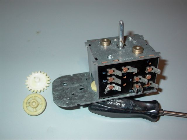
Post# 732676 , Reply# 79   2/3/2014 at 13:07 (3,732 days old) by JWPATE ()        

Grease lube was only used on the flat surface of the metal plate, upon which the gears reside. I also greased the axis shafts and the holes where they fit in. Silicone grease being used for this as I have confidence it will do no harm to the plastic parts.

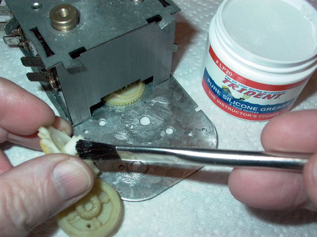
Post# 732677 , Reply# 80   2/3/2014 at 13:10 (3,732 days old) by JWPATE ()        

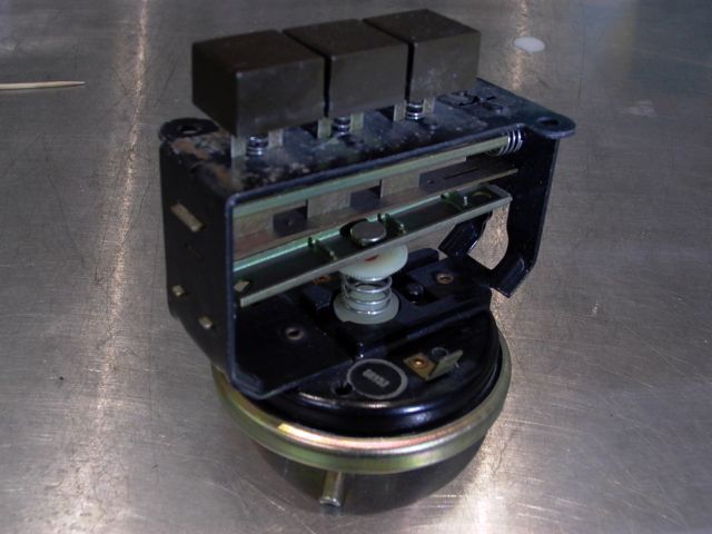
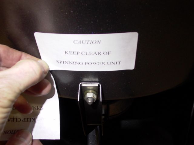
This looks like a dangerous toy does it not? And, certainly we must maintain our concentration when messing about with such a tool.

Post# 732678 , Reply# 81   2/3/2014 at 13:16 (3,732 days old) by JWPATE ()        

It does however, allow us to easily operate and observe the action of this little motor. Here it is running while a drop or two of turbine oil have gravity in their favor getting lubrication to the shaft.

While watching it you will be perhaps surprised at the slow speed of that pinion gear. Its speed, in revolutions per minute, is exactly one.


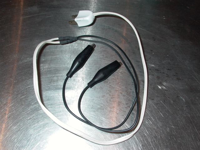
Post# 732679 , Reply# 82   2/3/2014 at 13:23 (3,732 days old) by JWPATE ()        

If we peer inside through one of the case holes it is possible to watch that second gear in the train make is periodic advances. At exactly one minute intervals it advances by six gear cogs, as seen through the case hole.

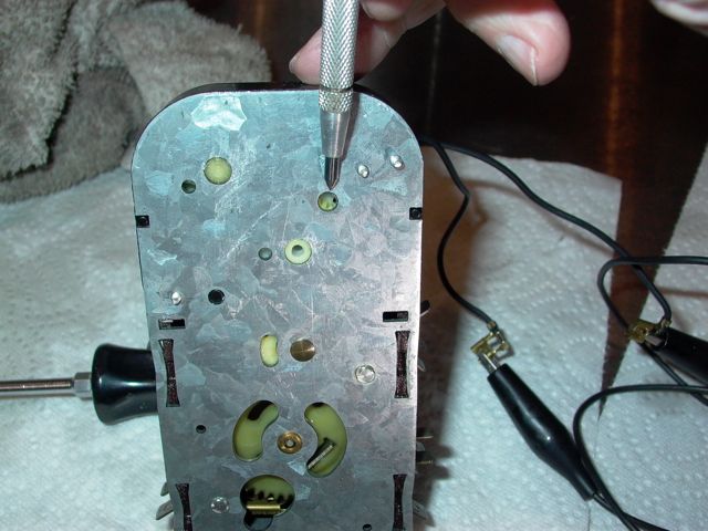
Post# 732680 , Reply# 83   2/3/2014 at 13:26 (3,732 days old) by JWPATE ()        

I suppose that is enough fun for now, with the control panel parts. Put the switches back where they belong, and hope they continue to perform as they have done these last 30 years.


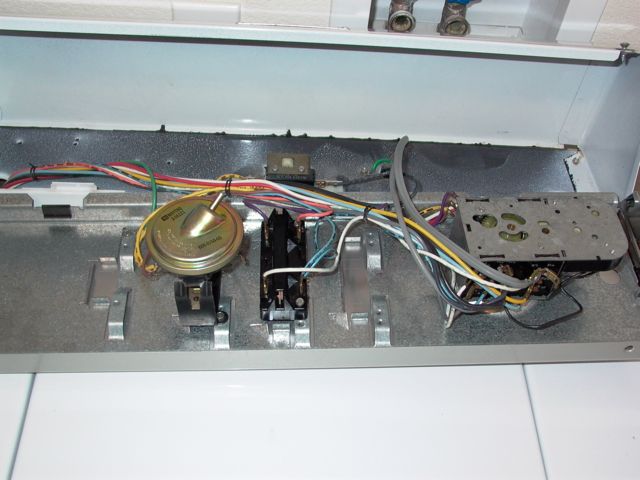
Post# 732686 , Reply# 84   2/3/2014 at 14:46 (3,732 days old) by Supersuds (Knoxville, Tenn.)        
Following this with great interest

supersuds's profile picture
It's neat seeing the inner workings of the timer, and your exposition is crystal-clear.

Post# 732730 , Reply# 85   2/3/2014 at 19:27 (3,732 days old) by beekeyknee (Columbia, MO)        

beekeyknee's profile picture
Looking good James. That jar of silicone grease would probably be great for your motor carriage glides, if you haven't already put it back together (better than Molykote). And also your new damper pads when you glue them back on. Where did you get that jar of grease, if you don't mind?

That's funny you mentioning paying attention when using the extension cord and alligator clips. I've caught my mind wandering while using one of those and then suddenly snapping back to reality.

B.


Post# 732753 , Reply# 86   2/3/2014 at 21:43 (3,732 days old) by JWPATE ()        

Yes, that pure silicone grease isn't that easy to find, unless you have a scuba/dive shop nearby. I got that jar from amazon.


Post# 732819 , Reply# 87   2/4/2014 at 13:09 (3,731 days old) by JWPATE ()        

Brian's recommendation to go back and change the motor carriage lubricant from molykote to pure silicone got me thinking. I finally remembered the photo on Brian's washer overhaul site dealing with the motor carriage and went back for another look. Sure enough, in the background is a jar of MAYTAG Poly Lube, and the label shows it is a silicone formula. So, now that I know what that little tube of lube in the carriage repair kit actually is, I dug it back out of the waste basket. For the third time now, I then took the carriage down, cleaned it thoroughly and re-lubed it using the Maytag Poly Lube. Also went online and ordered a couple of jars of the stuff for future needs.

Actually gaining a fair proficiency now with that motor carriage.

And, below a new brake assembly has arrived. Looks to be the same as the original, except the halves are no longer fastened using machine screws/bolts. With none of the innards being offered as spare parts, I suppose it makes sense to save a buck and just crimp the halves together.


Post# 732820 , Reply# 88   2/4/2014 at 13:18 (3,731 days old) by JWPATE ()        

I had hoped though to take the new unit apart before mounting it, and satisfy my curiosity about what a new friction liner looks like.

The other thing I wondered about was how much, if any oil was inside the new units when they ship out. From looking there at the oily surface in the center of this image, it becomes obvious that they did lubricate the new brake unit. Still one wonders how much? Should I just mount it and carry on?
Probably, then if it starts ever to make noise, I will add an ounce or so according to the service manual procedure.


Post# 732828 , Reply# 89   2/4/2014 at 14:06 (3,731 days old) by JWPATE ()        

A Tale of Three Bearings.

So turning my attention to the bearings and their condition/replacements, we look first at the most heavily loaded bearing in the washer, the radial or spin bearing.

At the top here is the original bearing, made by the respected Japanese firm NTN. It is a common size, stamped 6206Z. The first number (6), means it is a deep groove ball bearing designed for radial loads. The second (2) identifies it as a light duty bearing. The third and forth numbers (06) designate the bore size as 30MM.

The suffix (z) would have designated steel side seals at the time it was made (mid '80,s). Today some bearings have only one side sealed, and therefore the stamping system has expanded slightly. Today this bearing specimen would be stamped either the suffix 2Z or ZZ.

As I hold it and pressure the inner race back and forth in an axial direction, I can only just detect a slight looseness. It is certainly there though, and represents slight wear in the bearing cage. So I have decided to replace it.

First off, I ordered a replacement from one of the Whirlpool parts retailers and it has arrived. It is seen here on the left side. It has rubber side seals, and that difference is a debatable departure from the original specification. Generally I believe it is fair to say that the rubber sides will seal better, at least for a while. The steel sides though, will have less rolling resistance and generally longer life.

The real issue with the Certified Replacement Part from Whirlpool however, can be seen by looking through the clear plastic cover and reading CHINA.

So, today I went across town to the Belt and Bearing firm and purchased the bearing on the right side. It is a direct replacement of the original, being stamped 6026 2Z. This item is made in USA by SKF, and will be the bearing I plan to use.


Post# 732837 , Reply# 90   2/4/2014 at 14:30 (3,731 days old) by JWPATE ()        

Here, with the brake rotor bearing we find a somewhat more limited choice. The 30 year old MAYTAG bearing actually still seems sound enough to me. It is tight, smooth and looks well made indeed.


And, this is not a common bearing size but rather it is a special Maytag bearing.

The item inside the Certified Replacement plastic looks to be the same cheap quality we have seen before, calculated to just make it past the limited warranty period.

Given this choice, I have decided to clean and repack the original for further service. I expect to keep the replacement part, and have it as a spare if needed later.


Post# 732852 , Reply# 91   2/4/2014 at 15:58 (3,731 days old) by DigAPony ()        

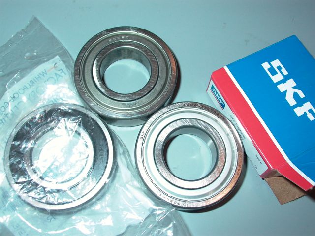
Nice to see such remarkable attention to detail and done quickly as well.

Good info, but going forward other high wear replacement parts will fail long before one of those original bearings.


Post# 733022 , Reply# 92   2/5/2014 at 10:38 (3,731 days old) by JWPATE ()        

This is a new set of outer tub mounting bolts with sealing washers. Both long and short bolts are still available, with the short one in the middle here.

The real story though is the sealing washers. My old ones were so hardened they looked more like polyurethane. These new washers are clearly a rubber seal, and they also are shouldered to extend down into the tub holes.


Post# 733105 , Reply# 93   2/5/2014 at 15:34 (3,730 days old) by JWPATE ()        

The so-called water injector system is next on the list. Notice the old system had most hose clamps in the single band style which we have seen earlier, and still wonder at how they went on. Only one of the clamps was a screw style, which allowed for adjusting the hose orientation at that fitting.

The new arrangement has all the clamps adjustable, and all in the open-slot style which will be replaced with higher quality clamps. Note also that the two at the nozzle housing are on backwards, and would have to be turned around anyway to prevent the screw mechanism from fouling with the washer sheet metal.

The plastic nozzle housing is a slightly different design, which would seem to allow some water drops splashing from the nozzle and sleeve arrangement to be captured without falling on the sheet metal side and base plate. Looks like an improvement over the old style.


Post# 733107 , Reply# 94   2/5/2014 at 15:37 (3,730 days old) by JWPATE ()        

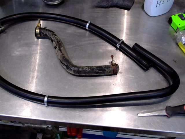
And it goes in place with ease. leave the hose clamps loose till the nozzle housing is fastened in place and then the clamps can be tightened with no strain on the hose sections.

Post# 733772 , Reply# 95   2/8/2014 at 15:36 (3,727 days old) by JWPATE ()        

While waiting for the last of the parts to arrive, I decided to have a look inside the dryer also. About all it seemed to need was cleaning out thirty years of dust and lint buildup. It is a model DG303 and I am regularly watching eBay every few days hoping to locate a service manual.

After cleaning it I again had a case of guilty realization that I have never really given that dryer a fair shot at getting its job done. The exhaust vent which came with the house required the use of flex hose and two 90 degree bends to exhaust the dryer.

So I did the only thing I could think of to do, and removed that built in exhaust vent and ordered a replacement. By carefully getting the height of the vent pipe about right, one can then adjust the dryer support legs to achieve a perfect line up.

Now there is no flex hose, no bends whatsoever, and just a straight path outside, which is only a foot or so away.

The patch for the original vent has only the first swipe of sheetrock mud, and will need at least two more before painting.


Post# 733775 , Reply# 96   2/8/2014 at 15:45 (3,727 days old) by JWPATE ()        

Outside, the patching is much larger because the original vent was in place before the stucco went on. At least two more stucco batches will have to me mixed up too, and look how damp that first one still looks after a full day to dry. Will take a while in this winter weather, but easy to do and no rush as the wind and critters are already barred entrance.

This stucco, like the sheetrock, had no backing here except for paper and insulation. So it was necessary in both cases to cut out plywood semi-circles and use them for screw anchors. Glad I did it though as this solution is much more satisfying than flex hose.


Post# 733777 , Reply# 97   2/8/2014 at 15:50 (3,727 days old) by JWPATE ()        

While I was diverted on the dryer effort, some more parts have arrived. The tub and base plate are back now with their powder coating completed. Here is one of the primary reasons for taking this route.

This is the main drain pipe, again protected from further rusting. For how long? Time will tell.


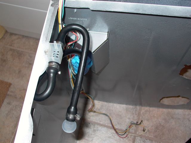
Post# 733778 , Reply# 98   2/8/2014 at 15:52 (3,727 days old) by JWPATE ()        

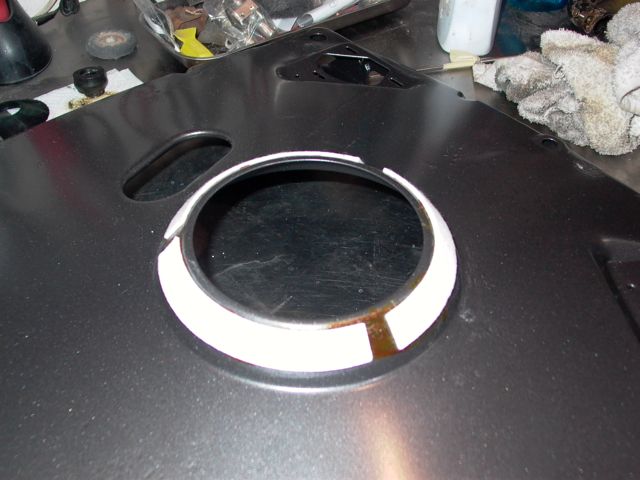
This sealing lip was the other problem area, and like the drain pipe it seems "good to go".

Post# 733784 , Reply# 99   2/8/2014 at 16:00 (3,727 days old) by JWPATE ()        

Next order of business will be these damper pads since they require time to dry also. The tube of MAYTAG glue was used here and there must be enough left in the tube for another hundred or so of these jobs.

Try to get the joints about equal in size and place the pads down about 3/32 from the lip. Easy to do, cause that is where they fit best.

Oh, and I sanded the new powder coat lightly first, with 180 paper.


Post# 733788 , Reply# 100   2/8/2014 at 16:11 (3,727 days old) by JWPATE ()        

Thanks very much to both beekeyknee and DigAPony, I was actually able to use both a new nylon pinion and new clutch washers in this transmission. Those parts are scarce now, but those forum members made it happen.

I changed those parts out, and filled it with oil. That container of MAYTAG transmission oil looks like a quart, but actually contains a bit more at 34 ounces. Directions on the container instruct us to use all of it on this transmission type. It fills the lower case just about to the brim.


Post# 733794 , Reply# 101   2/8/2014 at 16:20 (3,727 days old) by JWPATE ()        

These are unmarked, 5/16-18 hex screws, and such mild steel fasteners generally receive about 11-12 pounds of torque. I don't remember them being tight when they came out either.

So I started them down evenly with 7 pounds, and them went up a pound at a time, stopping when I reached 10 pounds. I would have gone another couple of pounds except for the aluminum case threads. So 120 inch-pounds just feels about right to me.

Other opinions?


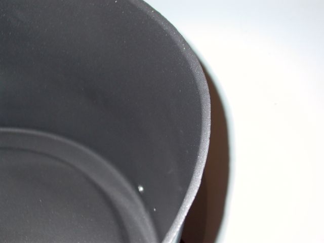
Post# 733844 , Reply# 102   2/8/2014 at 20:43 (3,727 days old) by beekeyknee (Columbia, MO)        

beekeyknee's profile picture
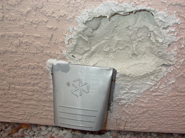
Looks good to me so far, James. In the order of your posts, the dryer vent looks close to the ground. If possible, you might want to consider digging the ground out a bit underneath the vent to give the air more room to exhaust and also to be able to reach into the bottom of the vent to clean out lint deposits. It's hard to tell. It may just be the way the picture looks.

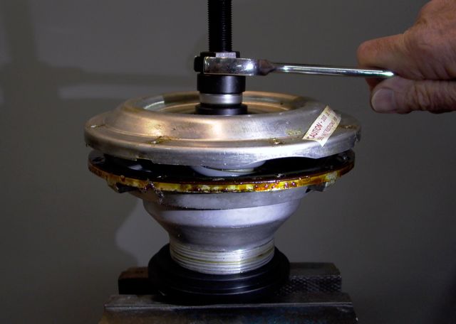
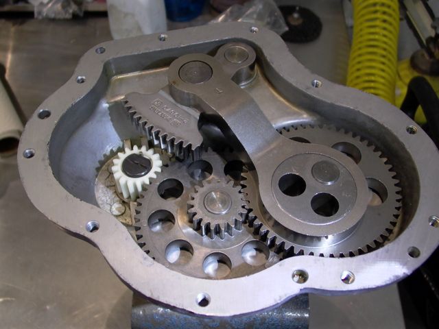
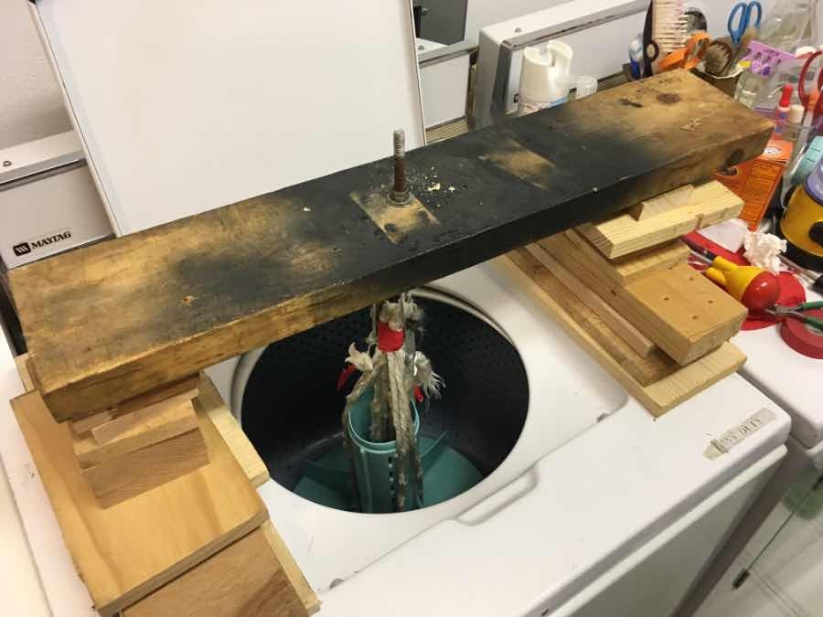
If looks are any indication, that tub looks like it should hold up well and the base looks nice as well. On a side note, the hole in the base is to help install the main drive belt. That isn't there on older models.

The fill in the transmission looks right. After the machine has been run a few times you can check the tightness of the bolts again with a wrench. I've found after the transmission has been back together for awhile, the gasket compresses a bit and the bolts can be tighten a tad more.

Out of curiosity, what did you put the transmission in while working on it? I've seen people use different things. One of my manuals says to drill a hole in your workbench for the purpose, but that's not always an option.


Post# 733855 , Reply# 103   2/8/2014 at 21:21 (3,727 days old) by JWPATE ()        

Thanks for following the progress Brian. Yup I think that photo may distort the distance a little. There is over seven inches from the bottom of the sheet metal to the rock surface. I checked it out with the dryer running and the air flow seems unrestricted.

I used a stout, steel sleeve mounted tightly in a vice. Then the transmission is just setting loosely inside the sleeve. I noticed that suggestion in the service manual about cutting a hole in the bench top and mounting an old brake plate under it to accept the transmission. That would certainly be secure and a pleasure to work with. Not for me though, this may well be a one-time effort.

Will be sure to remember and check the transmission bolts after a few days of use.


Post# 733877 , Reply# 104   2/8/2014 at 23:50 (3,727 days old) by DigAPony ()        
container of MAYTAG transmission oi

Very interesting. That Maytag transmission oil looks a lot like regular gear oil, not the brownish goop that one usually finds in vintage maytag transmissions.

What viscosity did appear to be?

Some say 90 wt. is acceptable, others say Maytag used 120 wt originally.


Post# 733930 , Reply# 105   2/9/2014 at 08:37 (3,727 days old) by JWPATE ()        

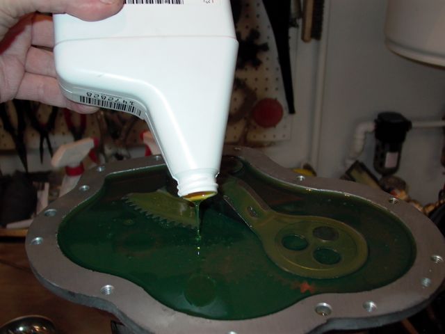
Yes, that MAYTAG HEAVY DUTY TRANSMISSION LUBRICANT looks like, and pours like 90 wt gear oil.

Post# 734008 , Reply# 106   2/9/2014 at 15:42 (3,726 days old) by JWPATE ()        

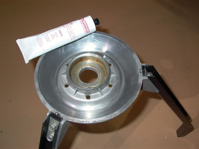
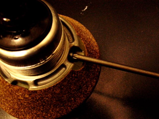
After powder coating, I especially wanted to clean the threads of that little 8/32 hole which provides a chassis ground for the motor circuits. While at it we may as well clean these four other threaded holes, then coat the threads with anti-seize.


Post# 734017 , Reply# 107   2/9/2014 at 15:54 (3,726 days old) by JWPATE ()        

Next I lubricated those three damper pads which had been left for their glue to dry. The pads come with one little tube each of MAYTAG Poly Lube, which we now know is a silicone grease. It it surprising how much grease they absorb, and the three little tubes were just about right.

Then looking here, at the damper surface where the pads will ride, it took a little while to really get this surface clean. It did have little sections of damper pad glue from the original fitting, but that came away with acetone and a soft cloth. Now I have lubed this surface also with silicone grease. The inside threads will soon accept the brake assembly, so they were coated with MAYCOR center seal grease.


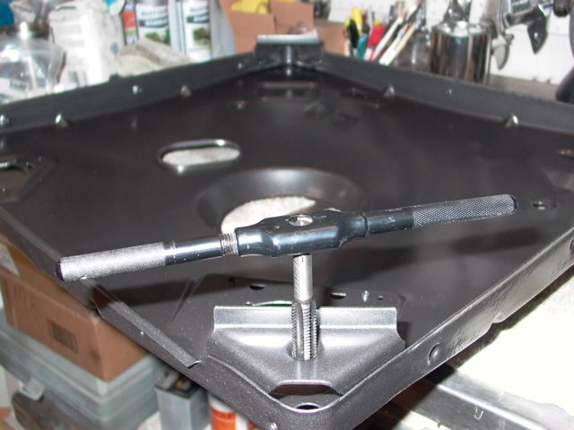
Post# 734022 , Reply# 108   2/9/2014 at 16:01 (3,726 days old) by JWPATE ()        

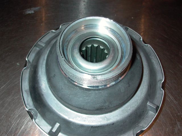
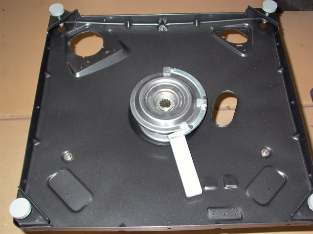
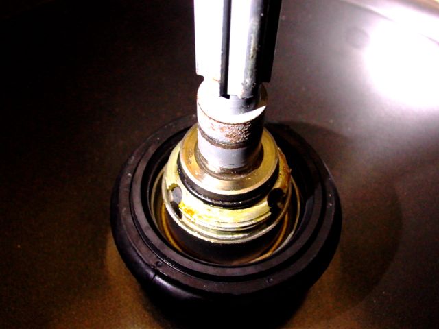
Now, lubricate the radial bearing surfaces and tap it down until it bottoms in that brake assembly recess. Then lubricate the brake assembly threads and also those splines which will engage the transmission lower case shaft.

Post# 734028 , Reply# 109   2/9/2014 at 16:08 (3,726 days old) by JWPATE ()        

Take the brake assembly down by hand until you can feel it snug up to the bearing. Then use the removal tool and tap it with a hammer a couple of times. No need to really whack it, all we are doing here is providing a firm grip on the outer race of that radial bearing. Then replace the retainer clip to prevent it backing out.

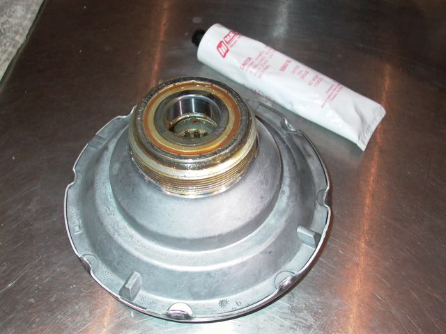
Post# 734031 , Reply# 110   2/9/2014 at 16:13 (3,726 days old) by JWPATE ()        

That's about all the weight I can handle before the base plate would become awkward for me. So I put it back where I found it.

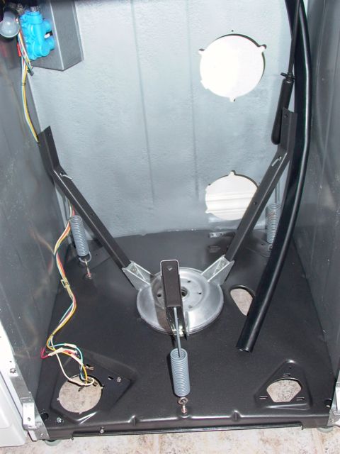
Post# 734049 , Reply# 111   2/9/2014 at 16:59 (3,726 days old) by akronman (Akron/Cleveland Ohio)        
Well,

akronman's profile picture
I know it's a NOSY question, but can I ask the price to powder coat a wash machine base? If I don't ask here, I'll never have a clue that it will or won't fit into the hobby budget.

If you answer, thanks. If you don't ,I know it's darn nosy to ask, sorry.

Thanks
Mark


Post# 734260 , Reply# 112   2/10/2014 at 15:53 (3,725 days old) by JWPATE ()        

Not too nosy akronman - I sent a PM so we don't go off topic here.

First order of business today was to level the washer. First I took it to the same plane with the dryer and then adjusted it to level and with no wobble or rocking.

Then the transmission is to go in. Lubricated the splines with central seal grease, and also did the helix threads for they will soon need it too. Replaced the upper shaft O-ring and placed the transmission back where it belongs.

Position the transmission so that it will not interfere with planned actions, for the brake assembly will prevent it moving for now.


This post was last edited 02/10/2014 at 18:40
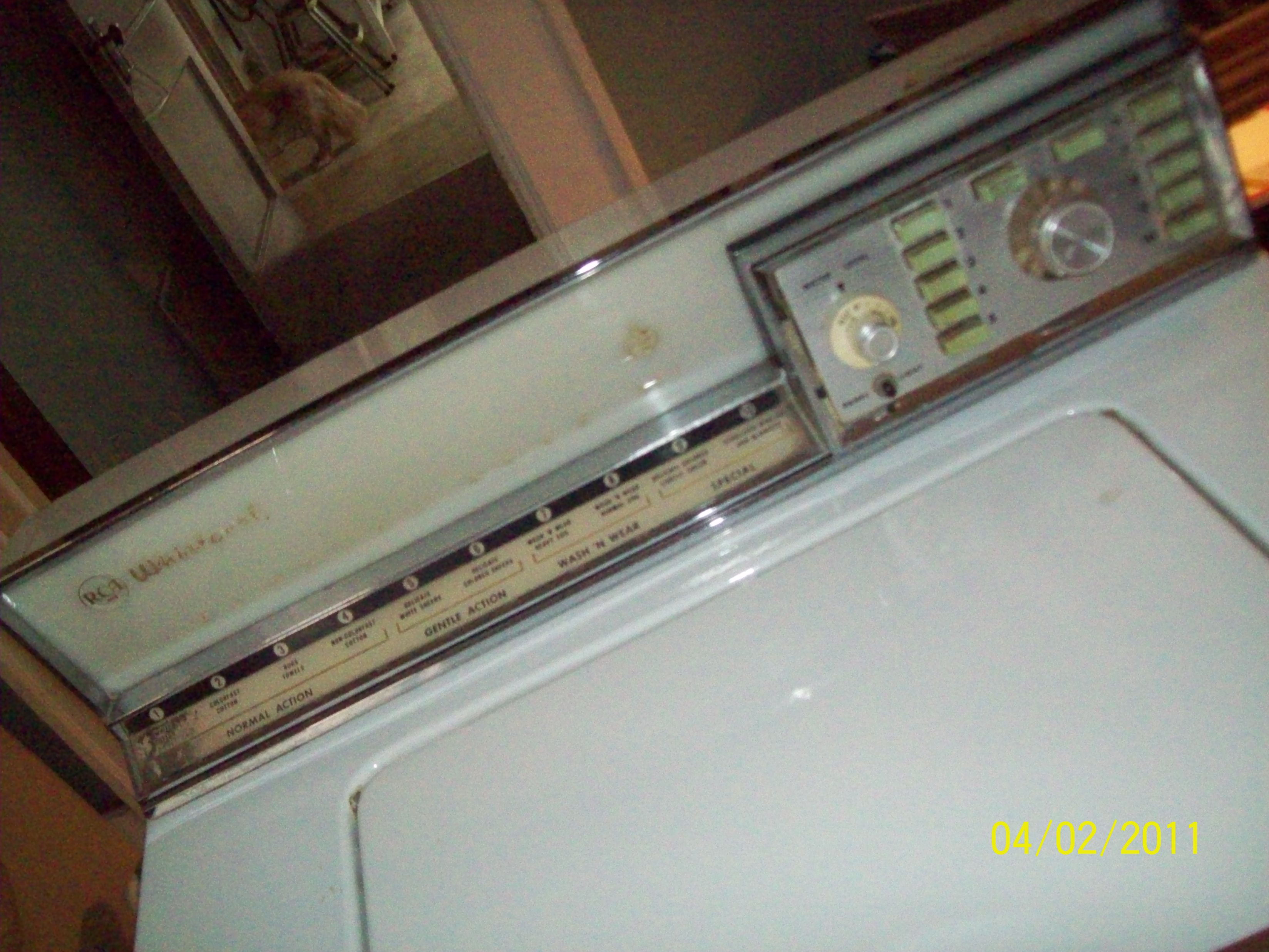
Post# 734261 , Reply# 113   2/10/2014 at 15:56 (3,725 days old) by JWPATE ()        

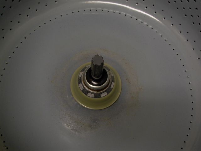
Lightly lubricated the outer tub bearing with Dow Corning 111 and it slipped into place without issue.

Then lubricated the bronze bushing with turbine oil.


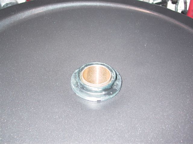
Post# 734266 , Reply# 114   2/10/2014 at 16:03 (3,725 days old) by JWPATE ()        

Here I am lubricating the transmission case with central seal grease, in hopes that it will inhibit the bearing sleeve from corroding to it the way aluminum and steel tend to do.

Used the same grease to lubricate the inner surface of the steel bearing sleeve.


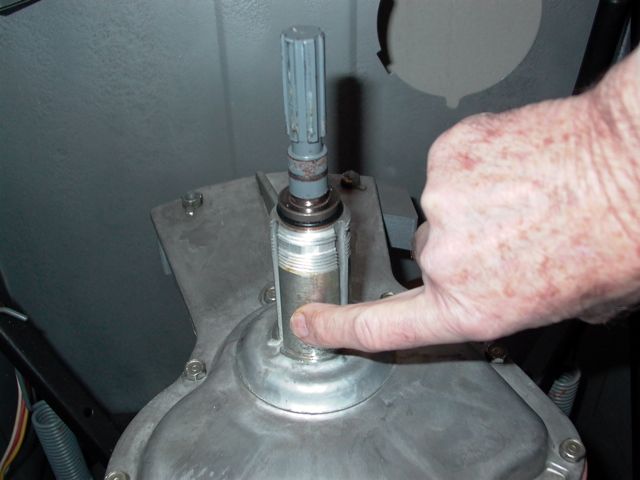
Post# 734269 , Reply# 115   2/10/2014 at 16:06 (3,725 days old) by JWPATE ()        

Slip the bearing sleeve in place on the transmission and then lubricate the outer sleeve surface with turbine oil.

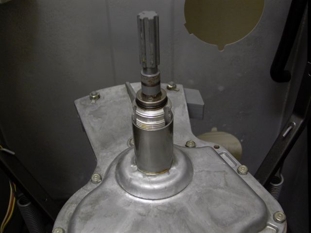
Post# 734271 , Reply# 116   2/10/2014 at 16:11 (3,725 days old) by JWPATE ()        

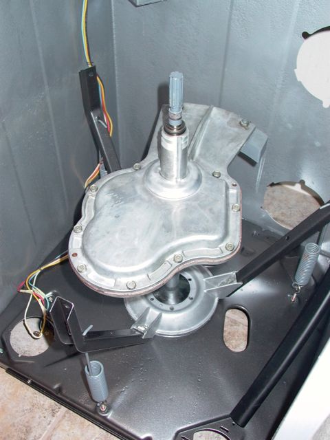
Bring the outer tub into action, pausing in this position long enough to attach the water level sensor hose. Then slip it down into place.

Post# 734273 , Reply# 117   2/10/2014 at 16:20 (3,725 days old) by JWPATE ()        

Now, while attaching the three tub mounting bolts, I realize why the longer bolts are needed in the two rear support arms. With new lock washers being used there is still just enough length to start the nuts a thread or two.

I coated the new rubber washers inside with DC 111 and carefully kept them from turning while tightening down the three nuts.

Here the caution note being replaced, as the original was blown away in the powder coating process.


Post# 734275 , Reply# 118   2/10/2014 at 16:28 (3,725 days old) by JWPATE ()        

I used again DC 111 to lube the inside of the lower sealing ring, then slipped it on the tub mounting flange with no problems, and being careful not to touch the teflon sealing ring on top.

Then, carefully libricated the aluminum mounting stem threads and those here on the transmission case, again with center seal grease.


Post# 734277 , Reply# 119   2/10/2014 at 16:44 (3,725 days old) by JWPATE ()        

I used the old style shaft seal in conjunction with the three lip seal on this new style mounting stem, as recommended by redcarpetdrew and beekeyknee in their step-by-step instructional threads. Both seals were packed with central seal grease.

Here I have taken the stem down hand tight and marked the positions of the three drain slots seen earlier in the transmission case. I will be tightening counter-clockwise another hammer blow or two, which will leave me in good position for set screw placement. The right leg of this tool is where the set screw recess is located.

This tightening will lock the steel sleeve of the tub bearing in place with the transmission case, and we only need to take out all slack. No requirement here for a heavy whack.


Post# 734282 , Reply# 120   2/10/2014 at 16:51 (3,725 days old) by JWPATE ()        

The new style mounting stems use T20 size thorx heads. Tightening the set screw down one can feel first contact with the transmission case threads. Then continue to crush through the threads until feeling greater resistance as the screw reaches the case aluminum. Stop there, and you will find that there are about three threads still showing on the set screw - as seen here.

Post# 734283 , Reply# 121   2/10/2014 at 16:57 (3,725 days old) by JWPATE ()        

Mount the inner tub onto the cork surface in the previous image. Center it as best you can inside the outer tub, place the load-spreading washer, and hand tighten the reverse thread nut. Then again a few light hammer blows to take out all slack..

Next, I lubricated the splines seen here and those inside the agitator with silicone grease and mounted the agitator. Put in the retainer screw after treating it to a new O-ring.


Post# 734289 , Reply# 122   2/10/2014 at 17:20 (3,725 days old) by JWPATE ()        

I used a new triangular seal for the tub cover, and lubricated both the seal, the outer tub lip, and the tub cover outer surface down about an inch or so with DC 111. Then fitted the tub cover in place with seal and stainless V-clamp. The tightening nut/bolt segments of the clamps I shifted to diagonal positions 8-2 instead of the original 10-4 positions. Otherwise all seems well. I just set the clamps reasonably firm then adjusted the tub cover as high as I could without it contacting the top cover while shaking the tubs around using the agitator stem. Then fully tightened the clamps.

The gap, seen at the end of the pointer worked out to be much less than before, and is about the thickness of a paint-stirring stick. We shall see how it works in actual operation.

This is a good time too for adjusting the main spring tensions. I tightened them such that after shaking the tubs around, they settle back generally centered in the top cover opening, but with a slight bias (maybe 1/16 inch) toward the front and away from the unbalance switch.


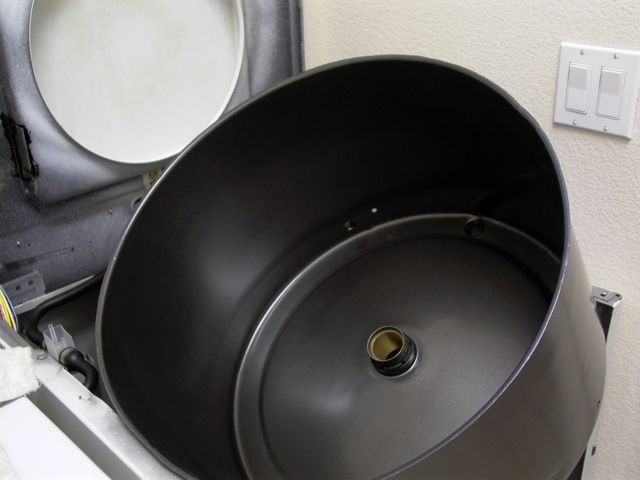
Post# 734332 , Reply# 123   2/10/2014 at 19:39 (3,725 days old) by mayfan69 (Brisbane Queensland Australia)        
Outstanding

mayfan69's profile picture
Hi James

I've been reading this thread with a lot of interest: congratulations on taking so much care and attention to detail on this restoration.

I'm sure your Maytag will give at least another 20-30 years of faithful service.

Cheers
Leon


Post# 734446 , Reply# 124   2/11/2014 at 08:21 (3,725 days old) by akronman (Akron/Cleveland Ohio)        
Wow

akronman's profile picture
This is one of the all-time professional rebuilds, and well documented. All I ever do is fix what's broke, seal up leaks, and de-rust and repaint. This, on the other hand, is as exact and complete as the engineers at the factory.

Keep up the good work and the pics and posts. Congratulations on your efforts and success!


Post# 734523 , Reply# 125   2/11/2014 at 16:13 (3,724 days old) by JWPATE ()        

Thanks for such encouraging comments fellows, and I am just amazed to see we have a world wide interest in this forum. Australians with an interest in our old MAYTAG machines, I would have never guessed it.

But back to the effort, and I have arrived at the motor replacement. I took the time to carefully map out a diagram of the hook-up wires, but it isn't even needed. Each of the connections is labeled on the motor, and the wires have connection numbers on them.


Post# 734526 , Reply# 126   2/11/2014 at 16:27 (3,724 days old) by JWPATE ()        

Next will be the water pump, and here I hit a problem. That old hose from the outer tub is far beyond its prime and so hard and brittle I would never trust it.

The Whirlpool certified replacement part is, as seen in the photo, too short for the job. That 1 1/4 inch gap makes the hose worthless to me. Can't return it either for it was outside its plastic bag before I caught the discrepancy with it. There are two part numbers listed for this hose on the MAYTAG site, and this item is the second number listed, 2-13045. Perhaps the other, earlier number, 2-12989 is available from another supplier. Hope so, and will start looking later today.


Post# 734528 , Reply# 127   2/11/2014 at 16:33 (3,724 days old) by JWPATE ()        

This photo shows the drain hose which I have been using for the past four years or so, connecting the washer to the house plumbing. It was never a MAYTAG hose, but just a stock item at Home Depot.

And it was always stiff, with a tendency to flatten and pinch off at every bend. That explains the reason for all those metal clamps to prevent it doing so.

It just may work here though, with the U-bend end connecting to the tub drain. I will cut a section and try to substitute it.


Post# 734529 , Reply# 128   2/11/2014 at 16:41 (3,724 days old) by JWPATE ()        

Well it will do, at least for a while. And it is an easy job to replace it. If unable to locate the correct molded hose for this machine I shall use a length of silicone hose, which can easily make those bends without any problem.

This substitute fit up well to the tub, but was too small and stiff to go on the pump. I had to soften it up with a heat gun before I was able to persuade it to cooperate. Even then It took that extra clamp to keep it from crimping off flat.


Post# 734530 , Reply# 129   2/11/2014 at 16:42 (3,724 days old) by JWPATE ()        

This post has been removed by the member who posted it.


Post# 734531 , Reply# 130   2/11/2014 at 16:48 (3,724 days old) by JWPATE ()        

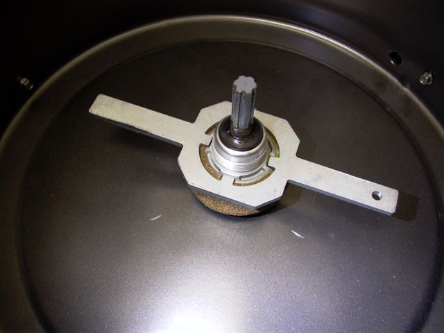
So now I can move on to these items. Lubricate the helix threads in the pulley, use a wheel bearing grease to pack the little brake rotor bearing, and tilt the machine back exposing the underside.

Post# 734533 , Reply# 131   2/11/2014 at 16:55 (3,724 days old) by JWPATE ()        

Screw the helix pulley on clockwise and check the feel as it releases the brake, engages the clutch washers and begins to turn the transmission and inner tub. Then back off and develop a feel for the point where the brake assembly is first made contact with. From that point, place the stop lug (flat side up) on a set of splines which will provide for between 1/4 and 3/8 inch of free play. I set it at the middle of that range - 5/16 inch.

When it is set to suit you, replace the special locking washer and retaining screw. Place the rubber cover over the lot.


Post# 734537 , Reply# 132   2/11/2014 at 17:05 (3,724 days old) by JWPATE ()        

Now position the new drive belts and adjust the pump belt such that when pinching the belt runs together at the mid point until the motor slide just begins to react, you will have 1/4 inch or less gap between the pinched belt sections. Tighten up the pump screws to secure this adjustment.

Post# 734538 , Reply# 133   2/11/2014 at 17:13 (3,724 days old) by JWPATE ()        

Now we are into the testing phase........the moment of truth!

First I connected up the water inlet hoses and the drain hose, then plugged her in.

First I selected spin cycle and let the machine spin dry for about 4-5 minutes. The spin was wonderfully quiet and smooth. Just as one should expect, I suppose, but was a real relief for me.

Now time to add water, so first I thought it best to also replace that rain shield over the motor.


Post# 734539 , Reply# 134   2/11/2014 at 17:25 (3,724 days old) by JWPATE ()        

Now I just set it for low load, cold water and let her rip.

Here the lid switch has been jury-rigged so we can see in. Ran it a full cycle just to see that all the controls and switches have survived my attentions. All seems well. Checked carefully for leaks and found none, so put back the front cover.

Since then, it has been in continuous service and is now on the forth load. This will continue also through the next day or so, as there is a great pile of laundry waiting.

And on that happy note I shall end this thread. Once again I would like to thank each member for following along and offering suggestions. Special thanks to beekeyknee and redcarpetdrew.

It is a great forum, and I thank you all for the assistance.

James


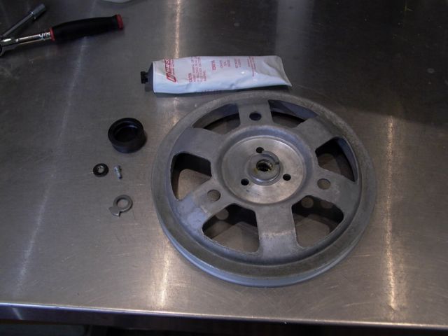
Post# 734579 , Reply# 135   2/11/2014 at 20:11 (3,724 days old) by jetcone (Schenectady-Home of Calrods,Monitor Tops,Toroid Transformers)        
Wonderful thread

jetcone's profile picture

it was so much fun following your technique and attention to detail. You did your machine proud, its a beautiful restoration.

Congratulations and thank you for sharing, I know along with other members here how much extra effort that takes.


jet


Post# 734631 , Reply# 136   2/11/2014 at 22:20 (3,724 days old) by beekeyknee (Columbia, MO)        

beekeyknee's profile picture
Hi James,

Congratulations. I could tell from early on that you were up to the task and one of those people that doesn't give up. It looks good. Fill us in a bit. Does the machine seem to run better and quieter than before? Any other details?

I trust you took the screw plug out of the front of that pump and gave it a good dose of Zoom-Spout oil?

B.


Post# 734701 , Reply# 137   2/12/2014 at 09:06 (3,724 days old) by swestoyz (Cedar Falls, IA)        

swestoyz's profile picture

James - I've been waiting with anticipation for your restoration to finish, and I'm glad everything went off without a hitch!  I'll echo Jon's sentiments in that your accomplishments have resulted in quite a beautiful restoration. 


I'll be really curious to hear how the power coating holds up after a year or so of washing.  This could be a nice alternative for preserving outer tubs and such.


Again, way to go!


Ben


This post was last edited 02/12/2014 at 13:45
Post# 734766 , Reply# 138   2/12/2014 at 14:15 (3,723 days old) by JWPATE ()        

                                                                      ......... SLOSHING, SLOSHING, SLOSHING................

                                                                        .........KEEP THEM LOADS A'WASHING.................


And I understand we are now on the eighth large load, and counting.  There was naturally a small mountain of sheets, clothing, towels and so forth waiting for this machine to be back in operation once again.  Today it has been as busy as a laundromat machine.  I believe we are now on the final load though.


All is well with the MAYTAG, it is smooth and quiet just as if it were new and we were back in 1986.  The single most noticeable improvement is related to the spin cycle.  Once again the towels come out of the machine only damp, just as they should do.


Yes Brian, I did lubricate that pump shaft and it was done with turbine oil. 


Post# 735345 , Reply# 139   2/15/2014 at 00:48 (3,721 days old) by redcarpetdrew (Fairfield, CA)        
BRAVO!

redcarpetdrew's profile picture
I stand and doff my Maytag hat to you and one of, if not THE most complete and awe inspiring resto's I've ever seen! That Maytag should be good for at least 17-27 years easy! I am simply in awe!

RCD


Post# 735461 , Reply# 140   2/15/2014 at 14:54 (3,720 days old) by kitty ()        
Just wondering about the spin clutch...

What type of clutch is it? Multiple spin drains would really wear out a regular one.

Post# 735562 , Reply# 141   2/15/2014 at 22:58 (3,720 days old) by redcarpetdrew (Fairfield, CA)        
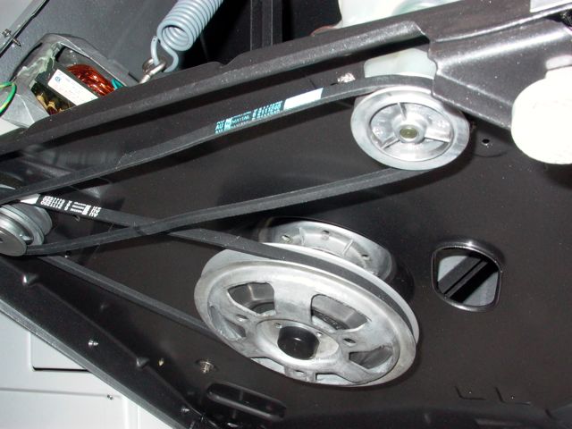
The Dependable Care spin clutch.

redcarpetdrew's profile picture
There really isn't a spin clutch as you would imagine it. On the two belt system, the pump belt is designed to get up to speed right away to start the pump out process. On the other hand, the drive belt from the motor to the trans pulley is designed to 'slip' at the motor pulley. So, when the Maytag goes into spin, the pump starts draining the water out right away while the tub starts to spin slowly, gaining speed, giving time for the load to empty providing less stress on the mechanism or 'clutching'...

The belts are designed to slip without premature wear out. One problem I see frequently is when the homeowner tries to replace the Maytag designed belts with plain automotive belts, which are NOT designed to slip. The drive belt tries to spin the full tub up to speed right away, causing belt damage or cause the motor to kick out on overload or possibly even be damaged from the stress.

Plain as mud, right?

RCD


Post# 735611 , Reply# 142   2/16/2014 at 08:29 (3,720 days old) by thefixer ()        

There is a spin clutch and it's right there in the first photo of this thread. It's inside the transmission and consists of one stationary washer disc and one rotating washer disc. When the drive pulley rotates and climbs the transmission input shaft the pulley radial bearing pushes up on and releases the brake while simultaneously pulling down on the shaft which squeezes the two clutch discs together. These will initially slip in addition to the belt slipping as the tub comes up to speed.

Post# 735619 , Reply# 143   2/16/2014 at 10:16 (3,720 days old) by combo52 (50 Year Repair Tech Beltsville,Md)        
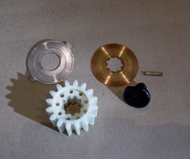
MT 2 Belt Spin Clutch In The Transmission ?

combo52's profile picture
The two disk washers under the pinion gear do not slip as the washers tub is coming up to speed while draining. The steel and copper washers are thrust washers that engage quickly and very completely as soon as the pinon gear pulls and the main drive pulley starts turning clockwise. If you have two people one can hold the transmission stationary while the other tries to turn the main drive pulley, it does not slip.

John L.


Post# 735655 , Reply# 144   2/16/2014 at 13:07 (3,719 days old) by thefixer ()        

Yes, thanks for that correction. The service manuals list them as steel and bronze clutch washers that take two to three rotations before the oil is squeezed out from between them and they lock up. That's rotations of the input shaft, not necessarily the tub as the tub isn't going to do much movement until that clutch is locked up. Sorry for the misinformation, I hate doing that.

Post# 735696 , Reply# 145   2/16/2014 at 18:49 (3,719 days old) by kitty ()        
OK...

So is that what's on my twin tub? It's really smooth and doesn't have much wear on it so is it that type of belt? It's over 30 years old, so if it's an automotive belt, it would always be in a bind. I pulled the tensioner strip all the way and it slipped a little over a decent amount of tension.

Post# 735698 , Reply# 146   2/16/2014 at 19:10 (3,719 days old) by kitty ()        
Something I forgot to add...

That rebuild/restoration is AMAZING! I don't think I could have done that. Your metal work is INCREDIBLE! Keep up the good work!

Post# 1040599 , Reply# 147   8/4/2019 at 01:17 (1,725 days old) by hobbyapocalypse (Northeast Pennsylvania)        
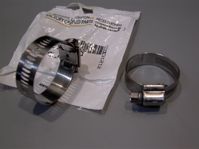
Hose clamp Reply #23

hobbyapocalypse's profile picture
Trying to figure out what is different about the clamp shown on the right. Is that what might be called a silicone hose clamp?

Post# 1040655 , Reply# 148   8/4/2019 at 12:08 (1,725 days old) by LowEfficiency (Iowa)        

lowefficiency's profile picture

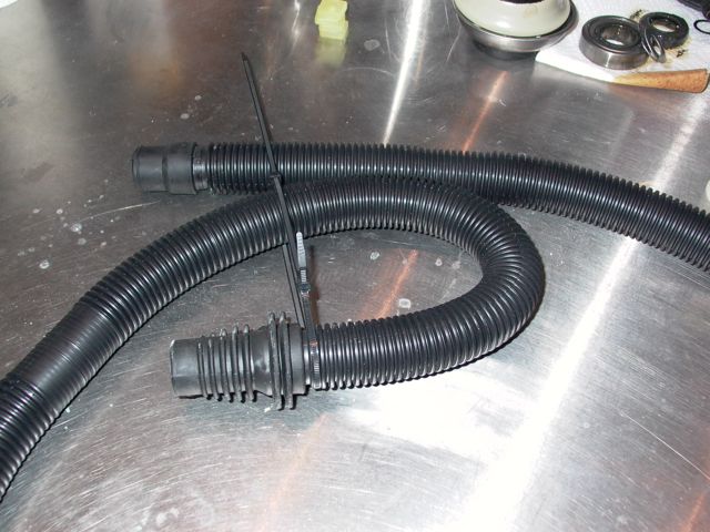
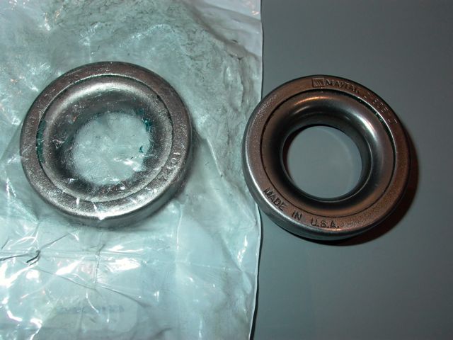
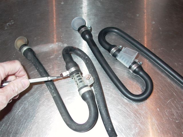
>> Trying to figure out what is different about the clamp shown on the right.


The difference is in how the tail end of the hose clamp is manufactured.

The clamp type on the left is more common, and has slots stamped all the way through the metal - they are holes that you can see through. The worm gear teeth engage these slots.

The clamp type on the right is different in that the stamping doesn't go all the way through - instead, it forms the metal into ridges. There are no holes, and you can't see through it. The worm gear teeth engage these ridges when you tighten the clamp.


The issue: With the clamp type on the left, what happens is that over time, especially if over-tightened, the rubber hose will begin to squish out through those holes. When you remove the clamp, it will leave a distinct impression of where the clamp had been, and sometimes the rubber will have been damaged. There are also times where the worm gear teeth will slice slightly into the top of the rubber hose through the band. The style on the right aren't always perfectly smooth (some are better than others), but theoretically, they would lessen this distortion of the hose and eliminate the small cuts.

There are lots of other ways around this issue - some worm clamps have an extra strip of smooth metal around the inside which guards the hose from those slots. Then there are T-Bolt hose clamps, the nut-and-bolt strap style, spring clamps, etc. Maytag used some nice hose clamps from the factory (not sure what that style is called off-hand), but later parts kits all substitute the cheaper worm drive clamps.

(re-attaching the original image for reference)


  View Full Size

Forum Index:       Other Forums:                      


Comes to the Rescue!

The Discuss-o-Mat has stopped, buzzer is sounding!!!
If you would like to reply to this thread please log-in...

Discuss-O-MAT Log-In


New Members
Click Here To Sign Up.


automaticwasher.org home
Discuss-o-Mat Forums
Vintage Brochures, Service and Owners Manuals
Fun Vintage Washer Ephemera
See It Wash!
Video Downloads
Audio Downloads
Picture of the Day
Patent of the Day
Photos of our Collections
The Old Aberdeen Farm
Vintage Service Manuals
Vintage washer/dryer/dishwasher to sell?
Technical/service questions?
Looking for Parts?
Website related questions?
Digital Millennium Copyright Act Policy
Our Privacy Policy