| click pictures
to enlarge |
My First Vintage
Television Restoration |
 |
Last February, while
out on my usual estate sale Saturday runs, I stopped at a sale in the
western Minneapolis suburb of Minnetonka. I usually go to between five and
ten estate sales every Saturday looking for vintage automatic washers. |
 |
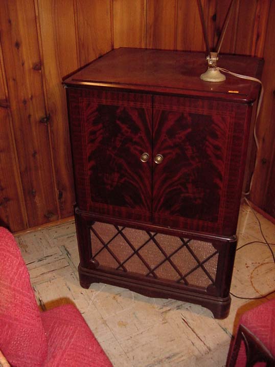
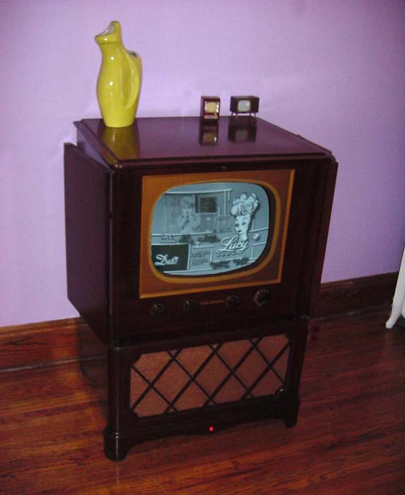
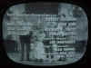
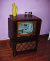
Down in the basement,
hidden in the corner, was this beautiful 1951 RCA wood consol television
set. Needless to say (although many have asked) it’s a black and white
set, color TV’s were not introduced until 1954. The cabinet was in very
nice shape and everything seemed intact with all of its original knobs.
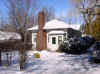
Since I had my camera with me, I was able to shoot a picture of the exact
house and spot in the house I found it in. |
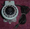 |
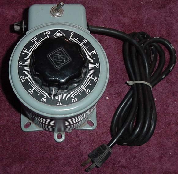
One thing your not
suppose to do to an old radio or TV that hasn’t been run for many years
is just go and plug the thing in and flip the power switch on. The best
thing to do is use a device called a Variac which allows you to slowly
bring up the power to a full 120 volts over the course of many hours,
sometimes days. You start it out about 20 volts and every few hours up the
control dial another 10 volts or so and watch for any adverse reactions
(you know, adverse like smoke, fire, explosions, etc) until you reach a
full 120 volts, just like normal house voltage. |
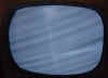 |
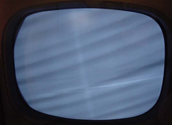
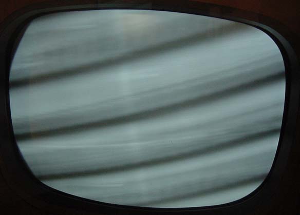
But I noticed that
this TV was already plugged in, so I assumed that someone else has already
tried it out at the sale today, I decided to just let it rip. After
warming up a minute the TV came alive with near perfect sound and a very
blurry, rolling, out of sync picture. Well that’s a good sign, at least
the picture tube worked. I figured it would be a fun new learning
experience; I always wanted to know how a TV set worked and now was my
chance. I bought the set for $30 and schlepped it home. |
 |
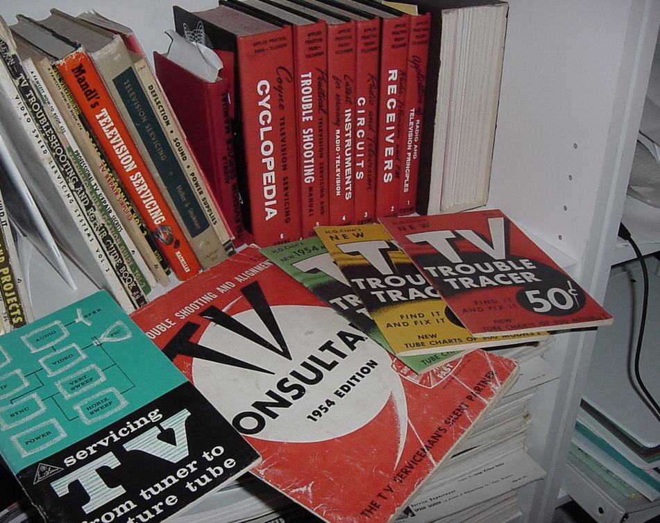
I have restored
over fifty vintage washing machines, but TV’s were a completely different
animal with more hazards involved like extremely high voltage and
dangerously high vacuums inside the glass picture tubes, so I needed to be
sure about what I was doing. I searched for a modern book on how to
restore old television sets, but like appliances, found nothing that been
written on the subject, so I spent the next few weeks reading all the old
1950’s TV repair books I could find. At first, I only understood about
one out of every ten words in these highly technical books, but as I read
the same thing written by different authors, who told the same story a
slightly different way, it all started to make a little more sense. |
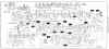 |
I also went downtown
to the main library to get a copy of the Sams-Photofact, for my particular
TV, which is a document of the wiring/circuit schematic and special
servicing information. Unlike washers or other types of major
appliances, post-war radio and TV service information was well documented,
for each major brand/model, by the Sams Company. Without this very
specific circuit information it would have been impossible for me to get
very far with this project. |
 |
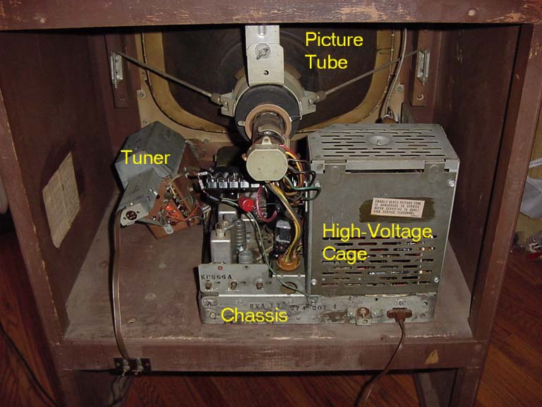
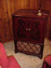
I was eager to begin,
so I removed the back and started to study the make-up of my new TV. There
are three main parts to a vintage TV, the picture tube, the tuner and the
metal chassis. The chassis contains all the tubes, wires, resistors,
capacitors, etc. that allow the flow of electrons through the system. In
this particular television, the picture tube is supported by brackets
directly inside the wood cabinet, with many other TV’s the picture tube
is supported and connected directly to the chassis. This means that I was
able to remove the chassis without having to remove the picture tube so
the chassis would be much lighter and less bulky to move. I unplugged all
the wires from the picture tube socket, yoke and speaker, removed the
supporting bolts from underneath and pulled out the chassis from the back. |
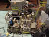 |
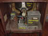
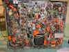
Here is the chassis
pulled out (post-restoration), although the top section doesn’t look
that much different from the pre-restoration version, except it was filthy
with dirt and dust and the poisonous selenium rectifiers were still in use
(which I promply replaced with safe modern parts). The first thing I did
was give it a thorough cleaning, then I took out each vacuum tube sprayed
the sockets with electrical contact cleaner. I then tested each of the 23
tubes and almost all of the tubes tested “good”. I still ordered an
entire set of new tubes from Antique Electronic Supply in Arizona,
although I later found out from more experienced collectors that tubes
rarely go bad, so that was probably a waste of money, but its all part of
the learning experience. |
 |
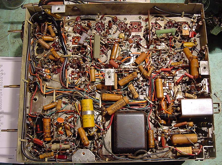
Working on the top section
of the chassis was the easy part. Now comes the hard part of the
restoration underneath the chassis, where the electrons travel from the
entrance at the wall plug through a major highway system of entangled
wires and spaghetti junctions to get to their final destinations. At first
look, I was completely intimidated at all this, I thought it would be an
impossible task to have to replace so many parts, in such tight-knit
locations, but with a little time and lots of patience it really wasn’t
so hard. |
|
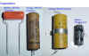
A capacitor is simply
an electronic device that fills with up with electricity and when its
completely full it spits out the electricity (discharges) into the circuit
and then begins to fill up again for the next cycle. A resistor on the
other hand is like an electrical water faucet, they simply slow down the
flow of electricity, so the higher the resistance rating a resistor has,
the slower the electricity moves, so the longer it takes to re-fill up a
capacitor after each discharge. In this TV there are 166 resistors and 132
capacitors, each one has its own job to do in the circuit. In vintage
TV’s most of the resistors should still be working close to the way they
were performing when it was brand new. Unfortunately, the paper and
electrolytic capacitors are a completely different story, as they age,
whether they are in use or not, many drift away from their original values
and some even being to leak electricity. That means of course that ALL of
the paper and electrolytic capacitors need to be replaced, as well as the two large can capacitors that are
mounted on top of the chassis, for a complete restoration. I knew this from talking to other vintage
radio/TV restorers, but I couldn’t find anything written on this subject
because vintage TV repair books do not take into account the fact that the
sets we are working on are over 50 years old. After some thorough
searching on the internet I found a wonderful web site
www.antiqueradio.org. Phil, the webmaster, runs a highly creative and well
organized site that includes a wonderful article he wrote on replacing all
of a radio’s or TV’s capacitors, commonly referred to as “recaping”.
I highly recommend this article for anyone considering restoring a vacuum
tube radio or television; I learned everything I need to about recaping a
television by reading this. |
 |
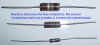
So I started replacing
those old capacitors with brand new shiny plastic orange ones, matching
the value of the new ones to the old ones as close as possible. I had quite
the job ahead of me, 51 out of the 132 capacitors under this chassis were
of the paper or electrolytic kind that need replacing. After replacing the
first 8 or so caps I decided to check my work to make sure I didn’t make
a mistake which could make things worse. So I reinstalled the chassis,
switched the TV on and I saw my very first improvement in the picture!
After adjusting the vertical hold control I was able to get the picture to stop
rolling vertically for the very first time since I had the set. Even
though the horizontal hold control didn’t stop the picture from moving
horizontally, it was by far improved over the original picture as I could
actually see slight movement of a televised scene between those diagonal
bars. WOW I thought, that was just too cool! |
 |
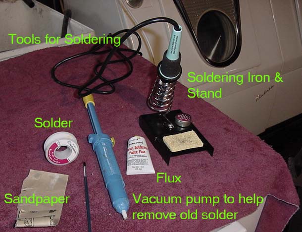
I couldn’t wait to
get home the next evening and continue on, after studying the circuit
schematic some more, I replaced another 10 or so capacitors specifically
in the horizontal synchronization (horizontal hold control) section of the
circuit. Replacing these capacitors is not a quick job, you must heat the
old solder on both connection points of the cap, remove the old solder
while its hot, then undo the old capacitor leads and remove it, clean the
socket connections, rewire in the new cap, resolder both ends in and
finally double check your work. One thing that made this easier is the
fact that modern 21st century parts are somewhat smaller and easier to
work with than their 1950’s counterparts. Each one took me an average of
10 to 15 minutes to do it properly. But it was worth it all. |
 |
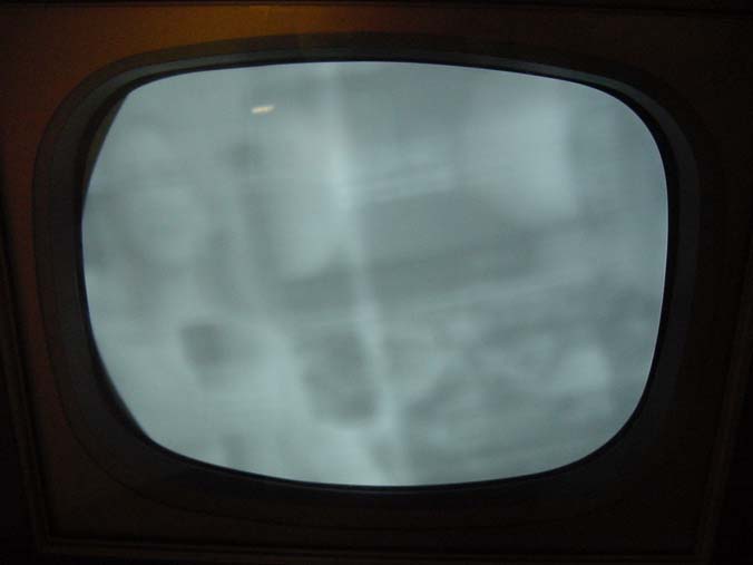
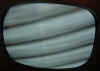
At 11:00pm that same
evening, I reinstalled the chassis, flipped the power switch on, held my
breath, waited 30 seconds for it to warm up and YES, I CAN SEE AN ACTUAL
TV PICTURE! It was a blurry, washed-out picture with a white line down the
center, but it was none-the-less a stable, recognizable picture. YAY David
Letterman has never looked so good! What a rush, I can’t tell you how
wonderful the feeling of excitement and accomplishment was. |
 |
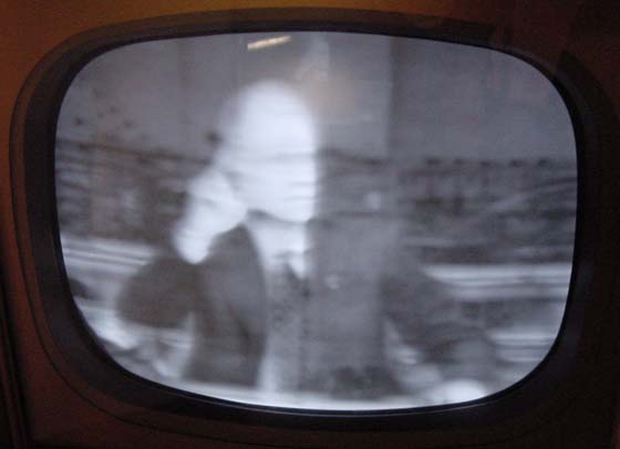
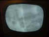
Continuing on over the
next few evenings, I now replaced another 20 capacitors and was 2/3rd’s
done. I reinstalled the chassis and received this rather startling good
picture, still somewhat out of focus, but better than ever before.
Unfortunately, now something weird happened to the sound. The only way I
could get good sound was to adjust the fine tuning to the point that the
picture was almost non-existent, in other words either I had a relatively
good picture and bad sound or vice-versa, just not at the same time. I
poured over the circuit diagram and rechecked my work, everything looked
fine. I simply reassured myself that hopefully recaping the other 1/3 of
the set would magically fix everything. |
 |
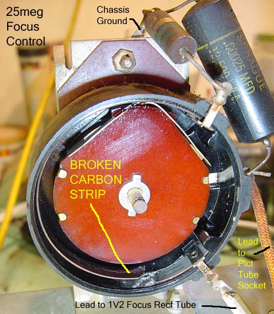
I started to wonder
about the rather blurry picture because I had completely finished recaping
the focus section of the circuit and I had begin to notice sort of a
burning smell coming out of the big focus control in the back of the TV.
So, like I would with a washing machine timer, I decided take the focus
control apart to investigate further. Check out what happened to the
control, a whole part of variable carbon strip had literally burned away.
Checking the parts list on the Photofact I see the control is simply a
variable 25 million ohm resistor. Resistors are measured in ohms, 0 ohms
means absolutely no electrical resistance up to “infinity ohms” which
means complete electrical blockage. All resistors are rated somewhere
between 0 and infinity ohms. Now I really needed some advice, so I turned
to the Antique Radio-Phono news group for help. This newsgroup, like
Applianceville is a discussion group, but for pre-1960 Radios, TVs and
Phonographs. I posted my message for help and received some wonderful
advice, including the following:
"If the control can't be repaired,
you could do this: Make up a 'daisy chain' of five 4.7 million ohm
resistors, plus a 1.5 million ohm (for a total of 25meg of resistance),
and connect it in place of the old control. You now have a voltage divider
with several taps. Find which tap gives you the best focus".
|
 |
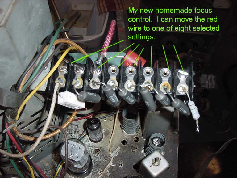
So I did just that,
but I used slightly different values than suggested mainly because a local
electronic store had lots of 1 and 4 million ohm resistors for sale, so as
long as they add up to 25 million ohms total, I would be just fine. I
purchased a junction block and cut it down to 7 sections and wired six –
4,000,000-ohm resistors and one 1,000,000-ohm resistor in series for a
total of 25,000,000 ohms. Then I could attach the focus control wire in
one of seven pre-set positions, 0, 4, 8, 12, 16, 20, 24 or 25 million
ohms. I found the best focus was at 16,000,000 ohm setting and that’s
where I’ll leave it. |
 |
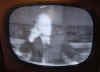
Now that the picture
was focusing properly, I knew this because I could make out each and every
of the 525 lines displayed on the screen, I could see another defect in the
picture. My TV was suffering from a “smeared picture” which simply looks like
objects have horizontal shadows protruding from them towards the right. Plus I still had the good sound/picture not matching up issue so
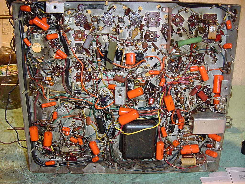
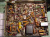
I went ahead a finished recaping the set. Finally, I finished
recaping the set as seen here in this picture of what the underneath of
the chassis looks like now. Unfortunately I still had my smeared picture
and poor sound problems. |
 |
The schematic lists
what the correct operating voltage level should be at over 100 different
wire connection points underneath the chassis, so I figured my next step
was to take voltage measurements at each and everyone one of these points
and if I find a particular reading was way too high or way too low, I
would at least know which area of the circuit was causing the smearing
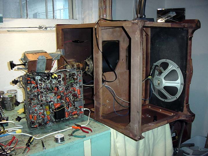
and/or sound problem. But in order to take these measurements you need to
have the TV turned on and in order for the TV to be turned on the chassis
had to be installed in the wood cabinet. With it installed, I can’t
safely reach underneath the chassis with the probes of my voltage meter.
So turning back to Phil’s antiqueradio.org I found he had restored a
similar RCA-TV and had this same measurement probe access problem, but he
figured out how connect the chassis from the outside by laying the wood
cabinet down on its side, up on the
workbench. After creating some extensions for the cables, I was able to
run the TV with the chassis outside of the cabinet, it would taken me a long, long time
to ever figure out that little procedure. Thanks Phil! Wouldn’t you know
it after all that, the measurements were all within 20% of where they
should be, many were within 2%-5%, but it was a great learning experience,
of course for extra safety I wore goggles, rubber dishwashing gloves and
always had rubber soled shoes on. |
|
|
So being completely
stumped I turned back to the Antique Radio-Phono news group and I received
lots of great advice, although many times I didn’t quite understand what
people were trying to tell me. Then I received this little tid-bit:
"you
could well have an open video peaking coil. These coils are wound over
resistors, so they would still be "in circuit" even with the
coil open. This can easily be checked by simply jumpering each one with a
SHORT piece of wire or metal object, (read two small screw drivers) while
observing the picture for an improvement".
Peaking coil, huh. So I
studied the schematic again and found there are five parts that were
labeled "Peaking Coil". So I searched them out under the chassis I found
out they looked like white cheese balls, covered in wax. Since they were
not capacitors or resistors, I had been previously ignoring them. I took a
small piece of insulated wire and used the wire to create a temporary
bridge so the electricity would jump around the peaking coil as if it
wasn’t even there. There were five to test, the first four made no
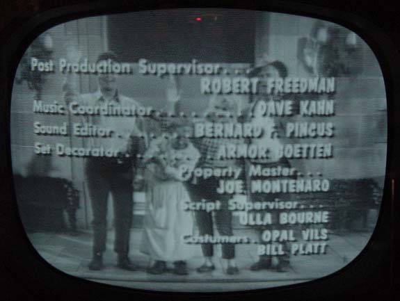
difference what so ever and my heart began to sink. Then I tried the very
last one to check and BOINK, the sound suddenly snapped into a perfect,
buzz free melody and the picture, why it’s BEAUTIFUL, the smear is was
almost completely gone. For the first time I could clearly see and read
all text that was printed on the screen and the best sound and the best
picture was now showing up at the same time. WOW, my heart was racing with
excitement.
|
|
So after a bit of more
advice from the newsgroup I decided to replace the one bad peaking coil
with a combination of two modern parts, even though the TV seems to be
working fine without it, I’m sure it has some good reason for being
there in the circuit. After soldering in the new parts I reinstalled the
chassis and POOF, no more picture. The sound was fine, but suddenly I
total lost both Horizontal and Vertical Sync and my beautiful picture was
gone! OH NO, I just was about to Old English the cabinet, bring the TV
upstairs, declare victory and watch a 1952 episode of The Adventures of
Ozzie & Harriet. So I figured those replacement parts were not working
the way I thought they should, I went back in and removed them and I
reinstalled the jumper wire that had worked so wonderfully before. Powered
up the TV and nothing, still no horz or vertical synch what so ever.
Doesn’t that just figure I thought, so close to success and now it’s
all gone. It took me over a week before I figured out when I was soldering
in those last two parts a tiny drop of solder had fallen 2/3rd down the
chassis and had landed between a terminal of four wires and the metal
chassis ground. The little splatter of solder was causing electrons to
bleed out of the sync separator circuit and go directly to ground. The
splatter was completely hidden and I didn’t notice it until after I had
removed wires and parts from that specific terminal as I was testing every
part in the sync circuit trying to figure out what went wrong. As soon as
I removed that solder my picture came back beautifully, I removed the
jumper, reinstalled the two parts that caused the solder drip in the first
place, and the picture has never looked better. |
 |
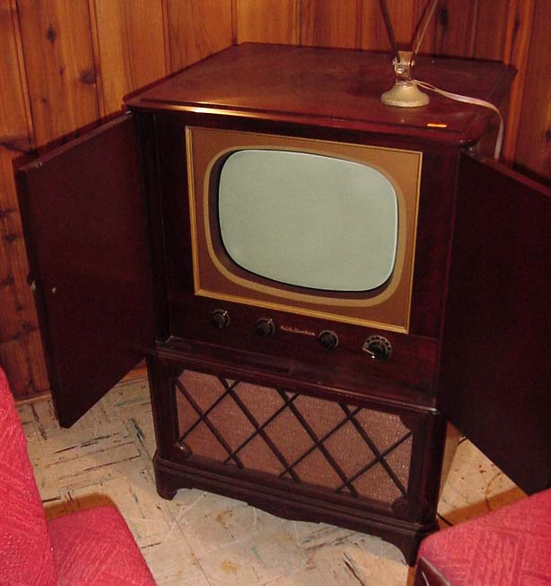
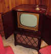
Tada, here is the
finished restoration! One Sticky Decision – OK well I’ve been using
the TV for a week or so and while I can comfortably watch the picture with
the room lights low, deep in my heart I know that there really needs to be
one final improvement. The picture tube has had a lot of usage over the
years, this makes them weak and they weaker they get the darker and more
washed out they become. Hawkeye Picture Tubes down in Iowa specializes in
rebuilding vintage television picture tubes. I inquired about having mine
rebuilt and I was told that rebuilding a tube like this would make a
difference like “between night and day” in brightness and clarity. But
the exterior of the tube in my television is metal, the majority of picture
tubes are all glass, but mine is a metal/glass combination. Unfortunately
their success rate with metal/glass tubes is only 50%. Under normal
circumstances 50% is certainly worth a try until I found out what happens
to the tubes that are “unsuccessful”, they explode or more accurately
implode from the stresses placed on them during the rebuilding process. So
here I sit, like I’m on Let’s Make A Deal and Monty Hall has just
handed me $250 which I can keep or I can give it back and take what’s
behind the curtain that Carol Merril is standing in front of. Either I’m
going to get a beautiful new Broyhill Living Room set or Jonny Olson
sitting on a 20 foot tall rocking chair dressed in drag as an old lady,
rocking away. What
a gamble! Decisions, Decisions, I can’t and haven’t decided yet…
More to come. |
|
|