|
Thread Number: 73440
/ Tag: Vintage Automatic Washers
60Hz Filter Flo on 50Hz |
[Down to Last] |
Post# 969756 11/24/2017 at 21:41 (2,336 days old) by chetlaham  (United States) (United States) |
||
|
| ||

|
| Post# 969884 , Reply# 1 11/25/2017 at 13:59 (2,336 days old) by potatochips ( ) | ||
|
Not to change the topic here but, did anybody notice that the filter flume shot out from the Front of the machine? And the fill nozzle was on the right side. As for the speed I agree, it sounds a lo different. | ||
| Post# 969941 , Reply# 2 11/25/2017 at 16:59 (2,336 days old) by Supersurgilator (Indiana) | ||
|
It's because it's the coin op version, thats why the flume is in the front. | ||
|
Post# 969944 , Reply# 3 11/25/2017 at 17:09 (2,336 days old) by jeff_adelphi (Adelphi, Maryland, USA) |
||
For ease of service---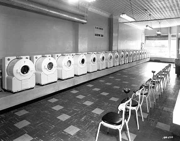 | ||
|
Post# 969951 , Reply# 4 11/25/2017 at 18:07 (2,336 days old) by chetlaham (United States) |
||
|
| ||
|
Post# 969971 , Reply# 6 11/25/2017 at 20:54 (2,335 days old) by chetlaham (United States) |
||
|
All true- GE FF use simple relay start induction motors and simple frequency dependent timers.
One thing that you want to do when running a 60Hz motor on 50 is to lower the voltage ie 120 60Hz to 100 volts 50Hz to prevent the motor from over heating. Though it looks like that washer is handling it well. | ||
| Post# 969972 , Reply# 7 11/25/2017 at 20:57 (2,335 days old) by Maytag85 (Sean A806) | ||
 | ||
| Post# 969974 , Reply# 8 11/25/2017 at 20:57 (2,335 days old) by iej (.... ) | ||
|
They're pretty big, well ventilated motors. I'd say they're likely very capable of handling a little extra heat. You might even find that the timer and other components are fine on 50Hz. | ||
|
Post# 969976 , Reply# 10 11/25/2017 at 21:03 (2,335 days old) by chetlaham (United States) |
||
|
@Maytag85: Because 50Hz just sounds sounds better!
Seriously though, its a bit obscure but I can copy and paste a pdf I have on the subject. @Iej: Those washer had some very reliable motors and timers, and someone on here even commented at how tough the enamel is on those windings. I expect that washer to go for some time- as it looks like it already has. | ||
| Post# 969978 , Reply# 11 11/25/2017 at 21:22 (2,335 days old) by speedqueen (Metro-Detroit) | ||
Reply to Maytag85 
I found a PDF online that might offer an explanation.
www.djtelectricaltraining.co.uk/d... All I can say myself is that 60hz makes more sense for the reliability of the rectification(diodes) and filtering(capacitors) circuits in electronics as there is less of a delay between polarity reversals. You would need bigger capacitors to filter 50hz vs 60hz. Also more people would be able to see the effects of alternating current at 50hz than 60hz in the form of light flicker. One aspect where 50hz makes more sense is the PAL television transmission standard being only one frame per second off of the moving picture standard of 24 fps and PAL at 25 fps. PAL has 2 fields per frame and one field per 1/50 of a second thus 25 frames per second. In PAL countries movies are simply broadcast slightly fast, a very simple process for telecine machines. The NTSC broadcast system used in the US uses 29.97(30 for simplicity, don't ask about why it is technically 29.97, very complicated answer) frames per second at 60 fields per second and is much harder to broadcast 24 fps moving pictures at because telecine(film to TV) machines must broadcast the same frame twice at regular intervals to make up for a faster TV frame rate | ||
| Post# 969979 , Reply# 12 11/25/2017 at 21:25 (2,335 days old) by speedqueen (Metro-Detroit) | ||
|
Oops, you already got a few answers, | ||
|
Post# 969980 , Reply# 13 11/25/2017 at 21:25 (2,335 days old) by chetlaham (United States) |
||
|
The origins of 60Hz as a Power Frequency
(Sorry for the poor copy and paste Some numbers and letters may have changed or lost altogether )
" Time is flying, never to return. -Virgil In 1891, Westinghouse engineers in Pittsburgh selected 60 Hz as their new power frequency. That same year, AEG engineers in Berlin selected 50 Hz as their new power frequency. Although much has happened since 1891, these two frequencies remain the principal power frequencies in use worldwide. Many people continue to be affected by the decisions on frequency standards made so very long ago. Travelers from Europe to North America often bring personal appliances with them that require an adapter to allow operation of the appliance on the �foreign� power available here. Sometimes, engineers reapply electrical equipment designed for operation on one frequency to a power system operating at a different frequency. As a result of these and similar common situations, questions arise about why there are two frequencies. Is it really necessary to have two frequencies? Why can�t everyone just change and use one frequency? Which is the �best� frequency? Questions about power frequency continue to arise periodically, and have done so for many years. Answers to these questions are not always as expected. People sometimes wonder about the geographical pattern of distribution for the two standard frequencies. In particular, why is one frequency used almost exclusively in some regions of the world while the other predominates in the remaining areas? This line bf inquiry sometimes leads those persons to suspect a conspiracy on the part of manufacturers to control markets or otherwise manipulate the world for their own benefit. People seem to love conspiracy theories. Other people speculate that there must be some pattern at work, the pattern tern based on the number 60. They observe that there are 60 seconds in a minute of time and 60 minutes to the hour. Or angular units include 60 minutes of arc to the degree and 60 seconds to the minute, so what about 60 Hz? After all, it seems only logical that 60 Hz is somehow an extension of the same rationale that produced these other units of measure. In particular the units of time, 60 cycles per second, 60 seconds per minute, 60 minutes per hour seem to be such a consistent pattern, more than could be explained by mere coincidence. However, the human mind is very good at finding patterns, even when a pattern does not exist. The Story of the Frequencies The story ofthe frequencies was told long ago. Charles Scott and Benjamin Lamme of Westinghouse both provided documentary accounts early in the 20th century [1, 2, 31. Lamme previewed his information in a discussion of an earlier paper by David Rushmore [4f.T hese authors restricted their attention to North American developments. Some narrative accounts also survive even today. These narratives are in the form of legend and story. Once upon a time, informal discussion between old-timers and new engineers was a common way for those entering the profession to learn about the lore and practice of engineering work. However, like the leaves ofautumn in the springtime, those old stories are mostly gone and forgotten. Now any person wishing to explore the circumstances surrounding adoption of either 50 or 60 Hz must rely on documents as primary sources of information. Prof. Harold W. Bibber (deceased) of Union College once offered some brief public remarks on the subject. The occasion was the 43rd Steinmetz Memorial Lecture in 1972. 1 Steinmetz was associated associated with GE; therefore he was a competitor of those at Westinghouse making decisions on 50 and 60 Hz. Although a competitor, his personal qualities, including insight and leadership, brought him respect. During the lecture, while Bibber recounted Steinmecz�s contributions to technical standards, he briefly repeated the story of the frequencies. By his account, �the choice was between 50- and 60-Hz, and both were equally suited to the needs. When all factors were considered, there was no compelling reason to select either frequency. Finally, the decision was made to standardize on 60-Hz as it was felt to be less likely to produce annoying light flicker.� Lamme�s latter account {If does not mention light flicker as being the deciding factor in the selection of 6O-Hz, and therefore the reader is left to wonder about both his earlier discussion {4] and Bibber�s version. Since neither party is now living, it is not possible to ask them to clarify their statements. When assessing the merits of various conflicting claims, historians usually place greater weight on contemporary wrirten accounts made by principals. On this basis Lamme�s account seems to be the more credible. (1, Nearly every year since 1925, the Steinmetz Memorial Lecture Fund has provided for public lectures by eminent scientists and engineers in honor of Charles Proteus Steinmetz. The Schenectady Section of the IEEE and Union College are cosponsors ofthese lectures. The 43rd Steinmete Memorial Lecture in 1972 was devoted to �Recollections of Charles P. Steinmetz,� rather than being about the science and engineering he represented. That year, speakers were selected from among those persons who had been personally acquainted with Steinmetz. Prof. Bibber, a protege of Steinmetz, was one of three lecturers to offer their personal recollections of him.) However, Prof. Bibber�s explanation is the more correct, although there have been times when even I was skeptical. Two pieces of evidence support the light flicker explanation, both attributed to L.B. Stillwell, a principal at Westinghouse. The first item is a brief article published in the IEE Journal before the turn of the 19th century. The second is a letter from the archives of the Westinghouse History Center in Pittsburgh. Both are firsthand accounts from Stillwell, one of the principals, stating that light flicker was the determining issue [5] [6]. Stillwell�s Account In November 1890, Stillwell and Byllesby returned from Europe. Stillwell was promptly given the job of investigating and recommending a lower frequency than the 133 Hz frequency that was their current standard. A few months later, an informal committee comprising Schmid, Scott, Shallenberger (by one account, it was Lamme rather than Shallenberger who was on the committee), and Stillwell recommended to Westinghouse management adoption of two frequencies, namely, 60 cycles (Hz) and 30 cycles per second. Stillwell recalled distinctly the final meeting of the committee at which this recommendation was agreed upon. They were disposed to adopt 50 cycles, but American arc light carbons then available commercially did not give good results at that frequency and this was an important feature which led them to go higher. In response to a question from Stillwell as to the best frequencies for motors, Scott said, in effect, �Anything between 6,000 alternations (50 Hz) and 8,000 alternations per minute (67 Hz).� Stillwell then suggested 60 cycles per second, and this was agreed to. Shortly afterward, the management of the company informally approved the recommendations of the committee and 60 cycles and 30 cycles became recognized standards for new work [ S , 61. Ironically, the first installation to use the new 60 Hz standard was the Pomona California plant described by Bill Myers 171. The irony comes from the role played by A.W. Decker, first at Pomona, where the new 60 Hz Westinghouse frequency standard was introduced, and then a year later at Mill Creek, where GE�s new three-phase system and 50-H~st andard frequency were both introduced [SI. Decker was in the right place at the right time to participate in making major changes to the state of the art in electrotechnology. Unfortunately, because of poor health, he did not survive long enough for his historic role to be properly recorded. It wasn�t until 1915 that the electrical pioneers began to document their deeds in an organized manner. If the question is �What is the best frequency?�, the answer depends upon when the question is answered and what application is involved. The story is not simple because it has evolved over at least 130 years. In that time period, fundamental changes in the application of AC have led to radical changes in the frequencies used [l}. The total period needs to be considered by dividing into different eras of electrical development. Experimental Period (1 82 1 to 1880) Electrotechnology has been developing since 1821, when Faraday showed that a compass needle is deflected by current flowing in an adjacent electric conductor. The years between 1820 and 1875 were an experimental period in which inventors conducted public experiments of interesting phenomena. Although AC was used during this period, its frequency was barely recognized. In 1831, Faraday demonstrated the principle of electromagnetic induction, where current flow in one conductor can induce current flow in an adjacent conductor by electromagnetic forces. This phenomenon leads directly to the use of AC, since magnetic flux linkages must constantly change in the coupled circuit to produce any sustained electrical effect. In 1832, H. Pixii developed the split-tube commutator for generator operation. His commutator opened up the field to DC applications, which then came to the forefront offurther electrical developments. Some people say Pixii�s commutator set electrotechnology hack SO years by allowing DC to take an early lead and postponing development ofAC until Tesla and Ferraris revealed the concept of polyphase current. This claim is not true because AC did continue developing during the period between 1830 and 1885. However, further development was severely retarded because electrical theories of that time were often based on hydraulic analogy. IC was difficult to imagine any useful work being done by �causing water to slosh back and forth in the pipe.� There were other naive opinions of that era that are equally humorous by modern standards. AC was regarded with distrust until engineers, like Steinmetz, Kennelly, Lamme and others, provided the conceptual underpinnings allowing practical applications. However, there were a few problems along the way. DC did not flow smoothly to all future applications, and AC was used to circumvent problems with DC. The Alliance machine was the first to provide AC power for commercial applications. In 1849, Nollet, professor ofphysics in the Military School of Brussels, took earlier machines by Pixii and Clark and increased the number of coils to obtain a stronger current [9]. (Prof. Nollet is not Jean-Antoine Nollet, a contemporary of Benjamin Franklin [lo].) Finally, Prof. Nollet arranged 16 coils on the same disk turning between the arms of eight magnets, and placing several disks upon the same axis, he created the Alliance machine (see Fig. 1). Unfortunately, the commutator sparked excessively, and it was necessary to replace it with slip-rings to obtain prolonged operation. Attention was turned to the availability of electric light for illumination of ships and lighthouses. The first such application of AC was in a lighthouse located at La Heve, France, in 1863. Slip-rings were used, and AC was produced because they did not know how to avoid commutator sparking and excessive wear. The Alliance machines had 16 poles and turned at 400 RPM, thereby producing AC with a nominal frequency of 53 Hz. The electrical potential was reported to equal 226 Bunsen cells, equivalent to 430 volts, an average. In this early period, these inventors were severely impeded, not only by limited understanding, but also by an absence of standard nomenclature. Frequency was not considered very important. As a result, today when we read their accounts, it is hard to follow their discourse and understand their results. They did not speak about hertz, as we do today, or even C.P.S. (cycles per second), as we did prior to 1968, when IEEE changed the designation. They spoke about alcernarions, full-alternations, turns, and periodicity. Reference to �Siemens type alternator operating at 1,000 turns and producing 16,000 alternations� meant a 16-pole generator operating at 1,000 RPM and producing an electrical output of 8,000 cycles per minute (133 Hz). The term alternation often meant only a half-cycle, but you can�t always be sure. This reference was to the Siemens type alternator used by William Stanley in 1886 to demonstrate a system of alternating-current distribution in Great Barrington, Mass. To be certain of the frequency actually in use, it is necessary to determine by calculation, using number of magnetic poles and operating speed. The Alliance machine at La Heve had 16 bobbins (poles) on each rotor disc and operated at 400 turns (see Fig. 2). When this information is used in Equation (1), the answer is 53-H~ Frequency= [Poles/2 x RPM/60] There were other applications of AC power for lighting. One of those was Jablochkoff Candles, used in Paris for illumination in 1876. To obtain equal rate of electrode consumption, they used AC power from a Grammes AC generator light Period (1880 to 1890) The Light Period is normally considered to have begun in 1882 with Edison�s Pearl Street station. In 1884, Dr. Hopkinson demonstrated AC electric power transmission over short distances and Gibbs & Goulard exhibited their transformers at the Turin Exposition. Meanwhile, Zipernowski, Deri, and Blathy at Ganz and Company were also developing their own transformers, In 1886, Galileo Ferraris was conducting public experiments with polyphase and William Stanley demonstrated his system of single-phase AC distribution for lighting, an extension of the previous work by both Gibbs & Goulard and Zipernowski et. aL at Gam and Company. In his demonstration system at Great Barrington, Stanley used a Siemens type alternator obtained by Westinghouse from Gibbs & Goulard in England. The alternator had 16 poles and was operated nominally at 1,000 RPM, hence 113 Hz. This was the beginning of t h e h i g h - frequency era in North America. Westinghouse followed the lead established by Stanley in Great Barrington and continued use of 133 Hz as a standard frequency. Meanwhile, T-H (Thomson- Houston) in Lynn, Mass., gravitated toward use of 125 Hz and Fort Wayne Jenny Electric used 140 Hz as their respective standard frequencies. There was no single high frequency used by everyone, but Lamme used the expression �approximately 130 Hz� to identify the group fl). Mranwhile, in Europe the trend was to use much lower frequencies. In 1889, Ganz and Company used 42 Hz, and Dobrowolsky at AEG used 30 Hz. AEG & Oerlikon used 40 Hz for their Frankfort-Lauffen transmission system in 1890. In 1891, AEG raised their standard frequency to 50 Hz. This was done to avoid any possibility of light flicker, as learned from the 40 Hz frequency used in the Frankfort-Laden system. That is where our story began. Power and Light Period In 1890, engineers at Westinghouse recognized that use of high frequency was impeding development of their induction motor. This was the primary reason for their change to 60-Hz. At GE, it was 1893 before they realized the need for a lower frequency. Henry G. Reist and W.J. Foster continued the work began by Danielson in 1890. When Steinmetz came to T-H in January 1893, work on the three-phase system was well under way. A few weeks after moving from Eichmeyer to T-H, Steinmetz found himself at Hartford, Conn. A problem with equipment sold to Hartford Electric had everyone baffled. Steinmetz was able to identify the cause as a transmission line series resonance, excited by harmonics of the 125- Hz power used. His proposed solution was to reduce the frequency of the system to one-half its initial value. This would have been 62.5 Hz, very close to Westinghouse�s 6 0 - ~ zs tandard. On further consideration, GE elected to use 50 Hz, the same as used by its European affiliate AEG. Later in 1893, when Mill Creek was commissioned in California, it operated at 50 Hz, the new GE standard frequency for power applications. A year later, GE found itself lagging behind Westinghouse in the sale of AC equipment and changed once again, this time to 60 Hz. Reist continued to advocate 50 Hz until the 1920s. Period of Systems Interconnection The Mill Creek installation placed much of Southern California on a 50-Hz path that remained unchanged until after World War 11. It was not easy to change over all that installed base of 50-Hz equipment, to operate at the new ~O-HZ frequency. Southern California Edison began planning in 1925 to make the conversion. It was not completed until 1948. England also experienced great difficulty in converting their local networks to a uniform frequency of 50 Hz. This was necessary to permit interconnection of the local autonomous networks into national grid. In the period 1924-1927, the Weir Committee considered the issue and selected 50 Hz as the new standard frequency CO be used by the also-new Central Electricity Board. Work on the conversion was not completed until 1938 at an expense of 17.3 million pounds I1 11. Japan experienced a different result. Their country was divided into two regions, each with a different standard frequency. IC began in 1889, when two Japanese engineers departed Yokohama for a tour of North America in search of electrical technology. They were looking for ideas to develop the Keage Canal project. They returned home with the necessary information and contacts to encourage them to use electric power. Their generator was made by SKC Chesney) in Pittsfield, Mass. SKC was formed by William Stanley after he left Westinghouse in 1889. Their frequency was 133 Hz, the standard frequency advocated by William Stanley long after everyone else realized it was too high for power applications. In 1895, AEG sold a 50-Hz generator to the power company in Tokyo and the astern half of Japan was pur on the 50-Hz path. A little over a year later, GE sold a 60-Hz generator to the power company in Osaka, and the Western half of Japan was put on the 60-Hz path (see Fig. 3). Conclusion Engineers have always used the �best� frequency for the purpose at hand, whatever the circumstances. Major changes in the particulars have occurred several times in the 100 years since 50 and 60 Hz were selected in 1891. The standard for power frequency was settled only in modern times. There were very many standard frequencies in use, even as recently as 20 years ago. The outcome was determined by operating conditions in the field, not exploitation of particular systems to limit competition. The efforts of engineers were directed to overcoming defects, not fighting each other. Acknowledgment This article is dedicated to E.A.E. �Ted� Rich, whose patient encouragement has inspired the research it represents. Any errors or omissions lie strictly with the author." | ||
| Post# 969981 , Reply# 14 11/25/2017 at 21:32 (2,335 days old) by cfz2882 (Belle Fourche,SD) | ||
|
50hz no problem most 60HZ motors are rated to also run without problem on 50HZ, BTW,Japan is a county with both 50 and 60HZ-when they began to modernize in the late 1800s,one section of that country bought 60HZ American equipment,the other section 50HZ German equipment. :) | ||
| Post# 970347 , Reply# 18 11/28/2017 at 03:42 (2,333 days old) by iej (.... ) | ||
|
This post has been removed by the member who posted it. | ||
|
Post# 970400 , Reply# 19 11/28/2017 at 14:42 (2,333 days old) by chetlaham (United States) |
||
|
Known for a while that a lot of standards existed, but seeing the list still makes me go wow. Then again I am not surprised, there are so many pros and cons to both high and low frequencies. Higher frequencies mean less flicker and less iron, while lower frequencies equal lower transmission losses and more favorable induction motors. All in all 50/60 is just a compromise adjusted for metric standards. FWIW I once calculated the ideal hypothetical frequency at 72Hz. But chances are as solid state advances 50 years from now everything might be headed toward DC.
| ||
|
Post# 970545 , Reply# 21 11/29/2017 at 07:32 (2,332 days old) by combo52 (50 Year Repair Tech Beltsville,Md) |
||
Reply # 6 | ||
|
Post# 970718 , Reply# 22 11/29/2017 at 23:25 (2,331 days old) by cuffs054 (MONTICELLO, GA) |
||
|
Does anyone have pics of old residential Euro electrical systems/equip? | ||
|
Post# 970736 , Reply# 23 11/30/2017 at 06:06 (2,331 days old) by chetlaham (United States) |
||
|
"When you lower the voltage on an induction motor the motor will run HOTTER and draw more amps, so it would be better to run the motor closer to its rated voltage of 120 volts."
That depend on several variables. Near its rated load and at 60Hz that would be correct. But at 50Hz, the risk of saturation can be greater warranting a reduction especially if the supply is likely to reach is upper voltage bandwidth. | ||
|
Post# 970737 , Reply# 24 11/30/2017 at 06:07 (2,331 days old) by chetlaham (United States) |
||
|
| ||
| Forum Index: | 
| Other Forums: |

|

|

|

|

|
 Comes to the Rescue!


