|
Thread Number: 81548
/ Tag: Vintage Automatic Washers
Saving a Unimatic - a Custom Imperial restoration |
[Down to Last] |
Post# 1055808 12/28/2019 at 15:37 (1,573 days old) by swestoyz  (Cedar Falls, IA) (Cedar Falls, IA) |
||
Hey gang - it's been a long time since I've had an open window of time to post something in the Imperial forum, and I'm excited to share with everyone a project that I worked on between August of this year, through the fall.
About 5 years ago a 1958 Frigidaire Custom Imperial set came to live in Iowa, after living with John and Tom for quite sometime, while the Maytag combo went to live in the Beltsville museum. The story I was told was that the washer was found while Tom was driving along the interstate in Atlanta and spotted the 'Ultra Clean' on a loading dock. I too would have been shocked to see such a sight while driving! Eventually the transmission made its way to Minneapolis for a reopperation, and from there it served Tom for several years and went to live in the museum. Knowing that not everything is going to come blemish free and in tip top operating condition, the washer appeared to not have been used in quite sometime and had a fatal issue - spin (with a roaring upper spin bearing), but no pulsation. At the time it was best to push the set in the corner and wait for a rainy day/different season in life. Between the summer of 2014 and now I even debated selling the set but decided to hold on to it, and since then I've gotten married, moved (outside of the house, one 18' U-Haul truck handled the whole collection) , had a daughter, and everything else that comes along with the typical American dream. The set, back in 2014: | ||

|
|
Post# 1055809 , Reply# 1 12/28/2019 at 15:43 (1,573 days old) by swestoyz (Cedar Falls, IA) |
||
|
A few years ago the first spark to light the fire to restore the washer came from a partnership with Bud (Sfh074). I had supplied him with several rubber Frigidaire items, including a mint 5432199 pulsator and the dispenser cap from the '58. We've all seem the fruits from Bud's efforts over the last few years as he magically recreated the soft rubber parts, making new items that were not only soft and pliable, but also the correct colors. His efforts will allow us to take restorations to the next level.
The second spark came this summer, when I had planned to visit Jetaction and our webmaster in Minneapolis. Ahead of this trip I decided to pull the mechanism so I could take the housing to Robert's to extract the upper spin bearing. From the get-go I knew things weren't great. Rust covered the pulsator shaft, long with rust inside the upper spin bearing and coating the bushing and spacer. Signs of water and rust were also evident inside the mechanism support seal. Also, I was surprised to see this mechanism had been outfitted with a replacement Delco motor from 1976, and a modified mount for a compressor style capacitor. It was also missing the trip solenoid terminal shield (oil pan under the solenoid). This post was last edited 12/28/2019 at 20:32 | ||
|
Post# 1055810 , Reply# 2 12/28/2019 at 15:49 (1,573 days old) by swestoyz (Cedar Falls, IA) |
||
|
Well, the next step to getting the housing off was to drain the oil. When I was growing up I was often found in the garage helping my Dad work on his drag car, and when you pulled the oil pan plug to find this, he always called it a chocolate milk shake - something you definitely don't want to find.
Water had mixed with the oil, and mostly water was left. The spin cage and base were seized solid and rust was lining the inside of the housing. | ||
|
Post# 1055812 , Reply# 3 12/28/2019 at 15:53 (1,573 days old) by swestoyz (Cedar Falls, IA) |
||
|
While visiting with Robert and extracting the bearing from the housing, the balance of the parts were soaking in mineral spirits. First and second round of cleaning actually went pretty well and all parts from the spin cage/base assembly came apart without too much hassle.
Date code on the base is early 1958, and the mechanism base is late '57: | ||
|
Post# 1055813 , Reply# 4 12/28/2019 at 15:58 (1,573 days old) by swestoyz (Cedar Falls, IA) |
||
|
The first item tackled during the reopperation was the spin cage and base assembly.
Out of all the various service manuals I've come across from reopperating Unimatics, the 1961 commercial manual Robert has posted on AE.org is by far the best for general use of reopperation. The '58 manual is also really good and covers small changes that happened through the years. Both manuals clearly it clearly walk through the assembly of the base assembly and which pin requires staking. All clearances checked out to be within tolerance (on the low side, too!). As for the bolts that secure the cage to the base I decided to use a dab of Locktite as some added insurance. Pro tip - spend as much time as you can on cleaning out the oil passages on these parts. They need to be perfectly clean - use compressed air and small bristle brushes to make sure no debris is left behind. In my case, there was a lot of sludge left over even after two rounds of cleaning with mineral spirits. Can anyone spy what I assembled backwards? This post was last edited 12/28/2019 at 20:38 | ||
|
Post# 1055814 , Reply# 5 12/28/2019 at 16:05 (1,573 days old) by swestoyz (Cedar Falls, IA) |
||
|
The next leg of the restoration became more of an exploration of the mechanism seal. It is widely known that the '57 and '58 Unimatic features a redesigned seal assembly (5879002), featuring a smaller mechanism nut and a new mechanical face seal, differing from the previous '47 through '56 lip seal and larger nut.
What isn't as widely known is that the top seal of the 57/58 Unimatic is the same mechanical face seal as the late 1955 thru 1958 Pulsamatic, which then is the same seal for the '59 through '64 Multimatics, AS WELL as the Rollermatics up through 1969! Yes the nut part of the assembly is unique to the Unimatic, but you can pop out the mechanical seal and replace it with a new 5439025 seal. In the early 70's GM sub'd out the 5439025 seal on the Rollermatics to the updated 633626 seal, making that seal backwards compatible back to the Pulsamatics and Unimatics! The bronze seal assembly on the bottom side of the tub remained the same for late �55 thru �58 Pulsamatics, 57/58 Unimatics, up to the end of the solid tub Rollermatics in 1969. First picture below - on the left is a Unimatic seal nut with a 5439025 seal set in place, and the original seal that was on the Custom Imperial. This post was last edited 12/28/2019 at 20:41 | ||
|
Post# 1055816 , Reply# 6 12/28/2019 at 16:14 (1,573 days old) by swestoyz (Cedar Falls, IA) |
||
|
While on the seal discovery path, parallel to those efforts I was getting the last of the parts disassembled and cleaned. I'm still shocked that the motor ran at all with the amount of oil coating the start switch terminals. Sheesh!
Also, it was at this time that I discovered that the torque plate was damaged. In the photos I've staged the torque spring and hub to sit inside the plate. The second shot you can see the broken part of the plate where the torque spring is able to twist into the plate. In '58 GM redesigned the plate with larger openings, of which I suspect was to allow for better oiling of the torque spring. It's amazing that this machine would still stop the tub after spin, considering the glazed condition of the brake pad on each plate. And, yes, that is oil coating everything within the motor. While the windings weren't soaked, everything else was. This post was last edited 12/28/2019 at 20:42 | ||
|
Post# 1055817 , Reply# 7 12/28/2019 at 16:23 (1,573 days old) by swestoyz (Cedar Falls, IA) |
||
|
Thankfully over the years I've found a fair amount of Unimatic parts, with one now critical part being a hub kit (5876907), which included a new hub plate and hub. I also had found one brake plate (5430571) and happened to find a second NOS plate during the restoration.
One critical measure the reopperating manual documents is the clearance between drive shaft sleeve and the torque plate, spec'd to be between .003 and .012. I don't have a picture of the feeler gauge in place, but in the first shot the gap is about .030! That isn't going to work at all, and may be the reason why the torque plate had a broken finger in the first place. Unfortunately the drive shaft diameter and collar diameter are not 'standard' to different industry thrust washers, leaving any over the counter generic option off the table. I reached out to Robert and he happened to have an extra thrust washer (.025, 5433461) that I could use. With the thrust washer in place the clearance came out to .005. Almost perfect! This post was last edited 12/28/2019 at 20:45 | ||
|
Post# 1055818 , Reply# 8 12/28/2019 at 16:35 (1,573 days old) by swestoyz (Cedar Falls, IA) |
||
|
Speaking of reading the reopperating manual carefully...
While reading up on the spacing in the previous post, I stumbled upon a mistake I made when assembling the spin cage/base assembly earlier (first photo). I had gotten the oiling hole orientation backwards, which would have caused the upper spin bearing to not receive any oil! I'm so glad I caught this when I did. Also - a must have tool to add to your Unimatic arsenal is a pair of Vacuum Grip 70-B pliers. These work PERFECT for removing the rings that hold the trunnion on place. GE also recommends using these to install the brake bands in the '56 through '59 solid tub transmissions. I used the snap ring pliers to reinstall the rings (and be careful you don't stab yourself when doing so...) This post was last edited 12/28/2019 at 20:47 | ||
|
Post# 1055819 , Reply# 9 12/28/2019 at 16:38 (1,573 days old) by swestoyz (Cedar Falls, IA) |
||
|
At this point I was getting ready for the full reassembly and needed to button up the NOS hub plate/brake assembly. Each brake plate had a layer of oil added to each brake pad prior to assembly. I also re-used the 1958 style pins and springs but used new cotter pins from the hardware store to hold everything together.
To assemble, use a 2x4 on the floor to press down on each pin/spring to get the cotter pins to slide through the back side. New assembly on the left, old on the right. | ||
|
Post# 1055822 , Reply# 10 12/28/2019 at 17:12 (1,573 days old) by swestoyz (Cedar Falls, IA) |
||
|
With the hub/brake assembly taken care of it was time to assemble the rest of the mechanism, starting with the oil pump. Take two small 2x4 and place the mechanism base upside down, and insert the bronze thrust bearing and drive shaft. I lubricated both with air compressor oil prior to installing.
This particular mechanism had the upgraded oil pump from the mid 60's, which includes a revised mechanical seal placed on the bottom of the pump housing and a new spring loaded plunger style pump, vs the early style finger pump. Rather than reuse the original gaskets and o-rings I opted to make new cork gaskets where needed, and procured properly sized o-rings for both the oil pump and trip shaft. Another issue I ran across was the cork gaskets supplied in the oil pump kit shrank considerably from its original form, which mirrors what I've seen with the cork gaskets for various pump housings as well. Thankfully all cork gaskets on a Unimatic are round are pretty easy to cut and I highly recommend getting a punch set to knock out the correct size holes. For the 6591693 oil pump kit, use these o-rings. I'll eventually do a write-up on the differences between the two oil pumps with the industry numbers for both versions. Large 7529598 - industry number 213 (Grainger 41UK89) Small 7529595 - industry number 115 (Grainger 41UK13) The revised oil pump directions are not printed in any of the reopperating manuals, so I've included it here. | ||
|
Post# 1055823 , Reply# 11 12/28/2019 at 17:17 (1,573 days old) by swestoyz (Cedar Falls, IA) |
||
|
With the rotor in place it's time to slip the motor case over the rotor and onto the mechanism base. Align the trip solenoid with the trip. Prior to installing the motor base I'd recommend checking the bearing. This one was locked up and required quite a bit of oil and motivation to get back on track. Also make sure to replace any spacers that may have been installed between the rotor and motor housing and make sure the start slider for the start switch moves freely and install the start switch. Both screws have different shoulder lengths so make sure you keep track of which screw goes where (tall shoulder goes towards the outside).
I used a Craftsman impact driver to install the screws for the motor cover - if you don't have one this is a MUST have for both assembly and disassembly of many fasteners we deal with. The motor housing will make an audible snap once it's been properly seated. With the screws torqued down it's time to install the motor fan. If there is any slop between the shaft and the fan you may end up with a rattly fan during operation. | ||
|
Post# 1055824 , Reply# 12 12/28/2019 at 17:25 (1,573 days old) by swestoyz (Cedar Falls, IA) |
||
|
Next up - pump housing. Both the bronze and carbon seal were in great shape so I reused both. All flaky residue was cleaned off with a wire bush on a motor. Add a dab of RTV to the bottom of the bellows seal and put a coat of compressor oil on the seal face using a cloth (not your finger). I use Locktite for the impeller screw and the impact driver again to install the impeller screw with a single screw installed in the housing and a screw driver holding the fan stable.
A new cork gasket was cut and and punched with RTV installed on the cover side, dry on the housing side. Prior to installation buff both sides on a wire wheel, if possible. This will also help during the final installation when installing the mechanism on the snubber. Align the X on the backside of the cover with the trip shaft and torque down the screws. After about an hour I came back and rechecked all screws. Pro tip - you may notice that all the fasteners are shiny but not new. Take the time to clean all screws on a wire wheel and taped holes with a tap. This will help ease the reassembly and ensure that all fasteners are torqued down without debris interfering with the fastener. This post was last edited 12/28/2019 at 23:11 | ||
|
Post# 1055825 , Reply# 13 12/28/2019 at 17:38 (1,573 days old) by swestoyz (Cedar Falls, IA) |
||
|
At this point everything has been reassembled from the base down to the pump. Now it's time to flip the assembly over to finish the top side.
I didn't document with photos the installation of the trip shaft and oil plug, but I did install a new o-ring for the trip shaft. In '58 they revised the trip shaft to have an o-ring seal from the trip shaft bore, rather than on the outside of the base. You can use a '58 trip shaft in all earlier bases if you happen to have a spare on hand. I haven't taken apart an earlier version yet to see how this seal is put together to understand if we can replace those seals with newer parts, yet. 1958 Trip Shaft seal o-ring 5929144: industry number 010 (Grainger 1KET3) For the oil plug you can more than likely reuse the seal, but I went to the hardware store and found a replacement. Moving on - the NOS torque spring and NOS hub are now installed on the drive shaft. I'd recommend putting oil on all surfaces to ease in installation. You'll want to twist it as you push it down in order for everything to seat properly. Next, install the hub plate/brake assembly over the torque spring hub, aligning the fingers of the spring inside the hub. Next, install the trust washer spacer (as needed, in this case I desperately needed one), the collar, pin, and pin retainer. Pro Tip - make sure the oil passages in the drive shaft are also clear of any debris or sludge. We need to make sure those upper spin bearings are lubricated properly. This post was last edited 12/28/2019 at 23:14 | ||
|
Post# 1055826 , Reply# 14 12/28/2019 at 17:47 (1,573 days old) by swestoyz (Cedar Falls, IA) |
||
|
Now the spin cage/base is reunited with the mechanism! The reopperating manual shows the use of a spacer tool to ensure that the cage is aligned and doesn't damage the drive shaft during installation. Take caution as you lower the assembly and use your fingers to adjust the drive gear in the base to align with the teeth of the drive shaft.
At this point I tested the mechanism to check for noises, and everything sounded great. There is enough surface lubrication from the assembly process to briefly perform this test without oil in the base, but I wouldn't recommend running the assembly without oil pumping for very long. Once the base is filled with oil and the spin cage and base are coated, perform a test to make sure oil is running through the mechanism up to the top oiling holes in the spin cage. The pressure of the revised pump is drastically higher than the original finger style. I had oil flying across the room within seconds after filling the base with oil, whereas in the past I've seen the finger style pumps take several seconds and the pressure is enough to push oil just over the bearing. Pro Tip: Oil. The service manual calls for 25 oz of oil, which is just a hair above 1.5 pints. GM provided an oil for reopperating Unimatic and Multimaic mechanisms without specifying the specifics of the oil (type or viscosity). Robert has used Air Compressor Oil in the past and I've found this to be the best option for Uniatmics. Air Compressor oil is compatible with soft metals, it is a non detergent oil, and it runs sooth and quiet through the mechanism. I grabbed this bottle of Mobil when I ordered the spin bearing and o-rings from Grainger. I checked the bottle after filling to just below the gasket line of the mechanism base and it was spot on at 1.5 pints. This post was last edited 12/28/2019 at 20:56 | ||
|
Post# 1055827 , Reply# 15 12/28/2019 at 17:52 (1,573 days old) by swestoyz (Cedar Falls, IA) |
||
|
Last step in documenting the rebuild for today is getting the mechanism housing installed. Use the special bearing tool* to install the nut over a new bearing (SKF number 6006 JEM / Grainger 36MC24) and stake the threads so the nut is safely installed. Brushing and spacer should be installed with the groove facing up on the bushing and notch up on the spacer (third photo of four below, second photo shows the bushing upside down).
I cut and punched a new cork casket and used The Right Stuff to seal both sides of the gasket for the housing. I let it sit over night and came back and re-torqued the screws. The reopperating manual calls for Permatex Number 2 on the threads of the mechanism nut, as well as on the gasket under the mechanism support. I bought a tube of this stuff years ago when I worked on a WO-65, so I'm not sure if you can still get it. Permatex No 2 is a tacky adhesive that I recall being used on other GM automotive items. I also used RTV on both sides of mechanism support nut washer to make sure oil wasn't getting out of the mechanism. This mechanism came with the later 7535394 anodized washer, vs the original version (5433471) made from a softer metal. I'll start working on Part 2 tomorrow - bench testing the mechanism and getting the cabinet ready for installation! This post was last edited 12/28/2019 at 23:20 | ||
| Post# 1055830 , Reply# 16 12/28/2019 at 19:07 (1,573 days old) by Repairguy (Danbury, Texas) | ||
 | ||
|
Post# 1055839 , Reply# 17 12/28/2019 at 21:08 (1,573 days old) by goatfarmer (South Bend, home of Champions) |
||
 | ||
| Post# 1055848 , Reply# 18 12/28/2019 at 22:55 (1,573 days old) by twintubdexter (Palm Springs) | ||
 | ||
|
Post# 1055884 , Reply# 19 12/29/2019 at 14:18 (1,573 days old) by swestoyz (Cedar Falls, IA) |
||
|
Thanks, gents! Joe I was hoping you'd see this post. Yesterday I was thinking about the stories you've told over the years of working at Western and rehabbing Unimatics when these were still just a used washer.
So, yesterday I left it off with the reopperation just about complete, with the next step in the process to do a run-in test of the mechanism. I tried two methods - the first was running on the bench with no tub, and the second with a tub bolted in place. The reason for the second approach was to see if torquing the assembly up against the spin cage washer and the spin bearing would decrease any drag on the overall mechanism (it did not). If you do attempt this please do not install the bronze washer securing the tub nut. I can't imagine having the mechanism free spinning dangerously with a tub installed. The service manual calls out the normal wattage ranges for a reopperated mechanism, specifying 215-225 watts. I took a page out of David's playbook and grabbed a Kill-A-Watt meter at Menards to bench test the mechanism and see how things were running. This is a brilliant tool - thanks for the tip, David! Oddly I couldn't get the mechanism to run any lower than say 290 watts, and it stabilized in the 305 to 320 range for both pulsation and spin. What I don't know is if the replacement 70's Delco motor and capacitor are any different than a 50's original, or if the revised oil pump puts more drag on the drive shaft, or if there is indeed something wrong with the mechanism itself (too tight of clearances, etc.). But, everything seems to run fine so I'm leaving things as is. It pulls below the rated 7 amps on the motor tag, so I took that as a positive. This post was last edited 12/29/2019 at 17:50 | ||
|
Post# 1055885 , Reply# 20 12/29/2019 at 14:25 (1,573 days old) by swestoyz (Cedar Falls, IA) |
||
|
Before assembling everything it dawned on me that the tub support needed cleaning as well. The remains of water mixed oil was on both surfaces, and the flange for the water bellows was rusty and needed some TLC.
The screws for the tub supports do not appear to be a common size/thread pitch that you can get at a hardware store, so take caution when removing these. Also, don't make the mistake I did and allow POR-15 to flow into the tapped holes. That made for a nightmare getting several of the screws installed. The tub bottom of the mechanism seal is shown in the last photo, with an NOS bronze washer and gasket installed, along with the original snap ring. Another oddity was the part number casted into the support - 5434039. That PN is for the 55/56 Unimatic tub support, but this particular support has the provisions for the 57/58 bronze seal assembly that cannot be used on a 55/56 mechanism and should have carried the 5436235 PN. This post was last edited 12/29/2019 at 16:33 | ||
|
Post# 1055886 , Reply# 21 12/29/2019 at 14:36 (1,573 days old) by DADoES (TX,�U.S. of A.) |
||
|
| ||
|
Post# 1055887 , Reply# 22 12/29/2019 at 14:37 (1,573 days old) by swestoyz (Cedar Falls, IA) |
||
|
In parallel to working on the tub, the outer cabinet and outer tub were cleaned and sealed up, as well. I make it a habit to clean the threaded holes for the leveling legs on all washers that come through for restoration, making the final install so much easier when trying to level out a machine. The '58 uses a much more robust leveling leg than the earlier style cabinets ('47 - '56). All leveling legs were cleaned on the wire wheel and lubricated with some lithium grease.
I also installed some flat washers between the leveling leg nut and the cabinet, for two reasons. One to ensure that the nut was accessible and nut recessed up into the cabinet while leveling, and two to help provide a more solid surface to stabilize the machine. The '56 I had at one time had gussets that would fit between the nut and cabinet, which was a brilliant way to help stabilize the washer during spin. The cross member also received some attention due to excessive oil and rust issues. The holes for the four bolts were cleaned with a tap and a new set of SS hex head cap crews replaced the old Phillips screws. I would strongly suggest this upgrade for any solid tub Frigidaire. It was also a good time to install the motor relay while cleaning the cabinet. This is cheap insurance for any Unimatic timer. Details on the relay will come up later. This also was a good time to add some POR-15 to any rust spots on the outer tub. | ||
|
Post# 1055888 , Reply# 23 12/29/2019 at 14:48 (1,573 days old) by swestoyz (Cedar Falls, IA) |
||
|
With the cabinet and mechanism buttoned up it was time to work on the second piece of advice that David provided. He suggested using some The Right Stuff to seal between the carbon face and the rubber boot on the 5439025 seal. It appears that water possibly got between the carbon and boot on the original seal (it was missing the original glue in several places) so all precautions were going to be taken to ensure water wasn't getting in a second time.
Three layers were applied between the boot and the seal, and after curing for a day the extra layer of protection was perfect. I used a small piece of rubber to cover the carbon face while working with the seal. With the mechanism in place in the machine I pressed the 5439025 seal into the nut. This isn't easy so take your time and make sure you don't touch the carbon face. I tried two different methods with the first being the soap trick Maytag suggests with their boot seal, and then dry. Dry did the trick. With Next was sliding the tub in place, and in these shots you can see the POR-15 applied to the water bellows flange. POR-15 makes for a wonderful surface for water to seal against, so even with the little bit of metal missing at the top of the flange, the ring that holds the bellows in place interfaces with the center of the flange. | ||
|
Post# 1055889 , Reply# 24 12/29/2019 at 14:54 (1,573 days old) by swestoyz (Cedar Falls, IA) |
||
|
The pan at the rear of the outer tub was in pretty rough shape. While they are porcelain coated from the factory, years of water spray can cause the corner seams to rot out. This particular one was still fully in tact but was starting to rot badly. It received a full coating of POR-15 to preserve what was left of it. The '59 and '60 pans are similar but don't trap water in the pan and can be used on the '58, if needed.
All new SS fasteners and rubber seals were installed on the pan, along with a new cotter pin holding the out of balance trip lever. The original tub seal was reused with an added seal added on top, all sealed with The Right Stuff. | ||
|
Post# 1055890 , Reply# 25 12/29/2019 at 14:57 (1,573 days old) by swestoyz (Cedar Falls, IA) |
||
|
With the outer cabinet finished it was time to disassemble the cabinet top and top panel for a full cleaning and part replacement.
The fill nozzle was full of hard water lime scale, so it was fully disassembled and cleaned with Lime Away, as well as the bottom of the top and lid/lid hinges. The hinges didn't get as clean as I'd like but they are good enough for now. An NOS motor protector was installed, along with the original florescent ballast and lid switch. I love that GM sourced this item from someone else besides GE, LOL. While the lid switch will be bi-passed I wanted the user to hear the almost silent switch when the lid is closed. | ||
|
Post# 1055891 , Reply# 26 12/29/2019 at 15:04 (1,573 days old) by swestoyz (Cedar Falls, IA) |
||
|
During the disassembly of the cabinet top I was surprised to see that the timer had a burnt out contact for the motor (BLUE lead) as the timer was able to run the motor during the initial test 5 years ago. Thankfully at some point in the past I had picked up an NOS rebuilt timer for a WCI-58. Date code on the replacement timer was the fall of '57 for an early run on the '58 models, with the original timer having a date code that correlated to many of the date codes found on the machine - January 1958. Super cool that the original timer was still in the machine!
All parts of the panel were cleaned, which included a rust stain between the plastic decorative panel and the tin painted panel behind it. At this point I had not completely bi-passed the lid switch wire from a previous bi-pass, but eventually I pulled out the second orange wire and looped one lead back onto the other terminal, completely avoiding the junction that was added at some point. | ||
|
Post# 1055892 , Reply# 27 12/29/2019 at 15:15 (1,573 days old) by swestoyz (Cedar Falls, IA) |
||
|
With the top now buttoned up it was time to test the water valve that came with the washer. The WCI-58/WCIR-58 were the only Frigidaire washers to come from the factory with a three temp, thermostatically control water valve (6560506), making this a pretty rare valve.
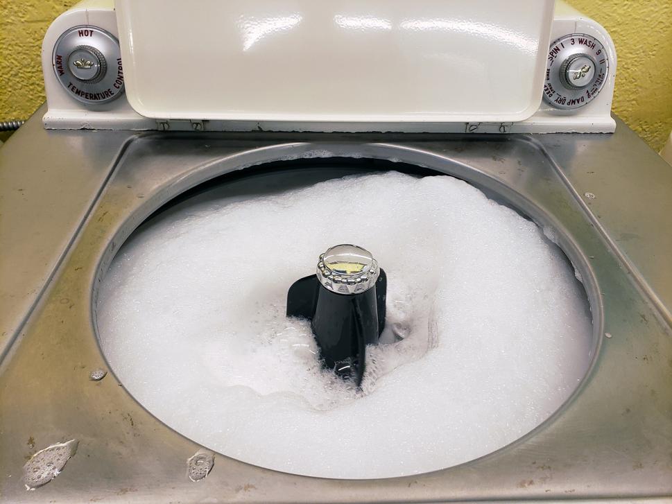
While the valve that came with the machine was a rebuilt replacement it leaked like crazy - out two of the solenoid seats as well as the thermostat. Rather than rebuilding it with new seats I thankfully I had an NOS valve for the machine. The new valve tested perfect - no leaks! With the valve now in place it was time to put one of the final items on - the bellows. I wasn't going to chance all of the hard work that went into the machine with used bellows, so NOS from the 80's were pulled out from the stock. The pulsator was installed with NOS gaskets on both sides of the pulsator (5433559), as well as some The Right Stuff under the pulsator nut for added protection. The original '58 soap dispenser column was installed with a new SS Phillips screw and washer. Phillips screws for the dispensers are much easier to work with than a hex headed screw. The cap was from the '57 Control Tower and the two rings were brand new rings from Bud. It's now time for a water test!! | ||
|
Post# 1055894 , Reply# 28 12/29/2019 at 15:18 (1,573 days old) by swestoyz (Cedar Falls, IA) |
||
|
Well, the water test wasn't quite leak free. The original hose between the added brass 90 degree elbow from the water valve and the fill flume split in half. This required removing the top to access the hose clamp at the fill flume to install a new hose.
The hose clamp was re-positioned so that the screw head can be accessed with the top on the machine, from the back side. With the split hose addressed, everything else ran perfect!
View Full Size
| ||
|
Post# 1055897 , Reply# 29 12/29/2019 at 15:27 (1,573 days old) by swestoyz (Cedar Falls, IA) |
||
|
With the water test complete it was time to button up the wiring and the back of the machine.
With the power relay (Grainger item 4A711) added as cheap insurance for the timer, I had the opportunity to piggy back a new hot lead from the motor protector up in the panel, down to the switched side of the relay, and a neutral line from the water valve to the control magnet side of the relay. The original blue wire down at the motor end had the heat soak sections cut out and now power the control magnet side of the relay, with a new blue wire running from the switched side over to the motor. The drain features a spare elbow and S hose I grabbed from a parted out Multimatic. These work great to replace the fitting that so commonly leaks on Unimatics. The long L hose was also from a parted out Multimatic. Lastly, the original flag terminal connector up at the timer on the BLUE wire was pretty fried and heat soaked. Come to find out that flag terminal connectors are tough to come by these days, but they can be found on eBay if you're willing to pay for them ($$) for originality sake. I picked up a package of 20 which should serve well for future projects. I also grabbed a oil pan for below the trip solenoid from a spare transmission. New screws all around for the back panel, including new flange nuts on the button side of the outer tub with new SS screws and washers securing the back panel to the outer tub. This post was last edited 12/29/2019 at 16:06 | ||
|
Post# 1055901 , Reply# 30 12/29/2019 at 15:37 (1,572 days old) by swestoyz (Cedar Falls, IA) |
||
|
Shortly after the restoration was done I reached out to Bud and he sent some of the final jewelry pieces to Iowa - a brand new '58 cap with the correct shade of turquoise and a replacement lint chaser ring.
Both look AMAZING on the washer, along with the spot on circulator (coral) ring. I can't wait to test out a new pulsator from him, hopefully soon. Bud - I can't thank you enough for all the effort and hard work you've put into this project. | ||
|
Post# 1055902 , Reply# 31 12/29/2019 at 15:40 (1,572 days old) by swestoyz (Cedar Falls, IA) |
||
|
With the restoration complete I've run about two dozen loads through the washer, and for the most part everything is working great. The top outer tub seal will leak just a tiny during spin on loads that are somewhat out of balance, and the brass elbow someone knocks against the outer tub.
Otherwise, mechanically this machine sounds about as good as they come. At some point I'll try to film a full cycle clip and load it up to YouTube, but for now here's a great clip of the Ultra Clean doing what it does best - washing some towels! | ||
|
Post# 1055903 , Reply# 32 12/29/2019 at 15:44 (1,572 days old) by swestoyz (Cedar Falls, IA) |
||
|
Thank you to everyone who helped along with the restoration, and for John and Tom holding on to this set for so many years.
I'm hoping to address some issues with the dryer later this winter. While I didn't get all the details covered about the restoration, please let me know if you have any questions where I may have left out some critical points. Here's some final glam photos of the restored, 1958 Frigidaire Ultra Clean washer and Filtrator dryer! | ||
|
Post# 1055904 , Reply# 33 12/29/2019 at 15:46 (1,572 days old) by swestoyz (Cedar Falls, IA) |
||
|
* special bearing tool
One final note -
Robert graciously lent me his spin bearing removal tool so I could finish out the project at home. I'm planning on making several copies of the tool this winter with plans to either sell some of the copies or make sure they are strategically located across the US for others to use. More details to come as I dabble at working a metal lathe and Bridgeport at the local Makerspace over the next several months! Ben
View Full Size
| ||
|
Post# 1055916 , Reply# 35 12/29/2019 at 19:22 (1,572 days old) by joelippard (Hickory) |
||
 | ||
|
Post# 1055928 , Reply# 36 12/29/2019 at 21:05 (1,572 days old) by Jetaction (Minneapolis) |
||
Amazing job as always | ||
| Post# 1055933 , Reply# 37 12/29/2019 at 23:05 (1,572 days old) by hippiedoll ( arizona ) | ||
WOWZERS!!
What a REMARKABLE restoration you've done here on that 1958 FRIGIDAIRE Unimatic washer. That set looks BEAUTIFUL! These would put ANY modern washer & dryer to shame, when it comes to looks & styling!
It bares repeating, THESE ARE BEAUTIFUL! I am so HAPPY that this restoration came together for you. WOOOO HOOOOOOO! :o) | ||
|
Post# 1055964 , Reply# 38 12/30/2019 at 10:48 (1,572 days old) by swestoyz (Cedar Falls, IA) |
||
|
Thanks for the kind comments, everyone. When folks outside the club ask why washers, why this hobby, one thing I like to mention is the community of friends here at AW as a huge reason why this hobby means so much to me.
Glenn - if you could get the mechanism up to Iowa I'd be happy to take a look at it for you. :) Joe - I've included a crude but slightly modified wiring diagram below, from a WI-57, along with updated photos with labels for the wiring. There are probably other ways of going about wiring in a relay, but this method has worked well for me. The key is to get power (hot line) from the protected side of the motor protector so that if the motor pulls too much current the motor is still protected. To do this I add in a new wire using a piggyback disconnect on the black lead between the motor protector and the timer, and run that new wire down to the switched side of the relay. Next, I add in a new blue wire between the other side of the switch on the relay over to the BLUE terminal on the trip solenoid. That takes care of the new power feed to the motor. The next step is to wire in the control magnet side of the relay. Take the original BLUE wire that went from the timer to the trip solenoid and run that to the control side of the relay. Last step is to get a neutral feed to the control magnet and a wire from one of the neutral sides of the water valve is usually the easiest place to tap into. Where you place the relay will vary based on the machine. For the '55 you may find that it is best placed up in the control panel, vs. where I located it down on one of the support legs of the outer tub for the '58. I also cut the original blue wire to fit nicely in the modified harness due to where I put the relay, but if you add in a relay in the panel of the '55, you may be able to take the original blue wire from the timer and connect it right to the relay, depending on if the '55 has 1/4 spade terminals vs. the round Douglas connectors. Feel free to shoot me a PM if you need help when you get to this stage on your '55. Ben | ||
| Post# 1055969 , Reply# 39 12/30/2019 at 12:28 (1,572 days old) by rickr (.) | ||
 | ||
| Post# 1055985 , Reply# 40 12/30/2019 at 16:13 (1,571 days old) by felix (S�o Paulo - Brazil) | ||
|
congrats from Brazil! | ||
|
Post# 1055988 , Reply# 41 12/30/2019 at 17:06 (1,571 days old) by gansky1 (Omaha, The Home of the TV Dinner!) |
||
 Really great documentation of the 58 rebuild, glad to see it shine in your basement. I've added the motor relays to my unimatics for some time now (it was Ben that researched what we needed originally from Grainger) and it solves the timer-stress problem once and for all.
Great job, as always, Ben and congrats on your efforts coming to such a beautiful finish. | ||
|
Post# 1056000 , Reply# 42 12/30/2019 at 18:25 (1,571 days old) by peteski50 (New York) |
||
Frigidaire! | ||
|
Post# 1056011 , Reply# 43 12/30/2019 at 21:06 (1,571 days old) by Unimatic1140 (Minneapolis) |
||
 | ||
|
Post# 1056012 , Reply# 44 12/30/2019 at 21:08 (1,571 days old) by joelippard (Hickory) |
||
|
| ||
|
Post# 1056016 , Reply# 45 12/30/2019 at 21:42 (1,571 days old) by askolover (South of Nash Vegas, TN) |
||
|
| ||
|
Post# 1056047 , Reply# 46 12/31/2019 at 09:47 (1,571 days old) by swestoyz (Cedar Falls, IA) |
||
|
Thanks again, guys. While going through the motions of the restoration it became evident early on that this would be a great opportunity to document a full Unimatic rebuild.
With the rebuild done I just wish that 1957/1958 had not been recession years within the US economy and that more WCI-58 washers existed today so everyone that wants one could have one. I'm hoping to do a write up on Unimatic oil pumps here shortly, and at some point dabble in 're-shoeing' the brake plates with new pads (thanks Bud for the tip on the material - .060 sail cloth!), as well as exploring the lip seal version of the mechanism support nut to see if we can install a new lip seal for the '47 through '56 models. Lastly, documenting my first experiences of machining with the creation of additional bearing tools! Ben PS - I just re-read through this post and I apologize for the many grammatical errors throughout. Most of it was written live on the site, under the gun of taking care of my 19 month old daughter, LOL. Wish we had a way to go back and do approved edits on potential archival posts ;) | ||
| Post# 1056123 , Reply# 47 1/1/2020 at 07:26 (1,570 days old) by christfr (st louis mo) | ||
 | ||
| Post# 1056142 , Reply# 48 1/1/2020 at 12:27 (1,570 days old) by cornutt (Huntsville, AL USA) | ||
|
This is fantastic work. Reading and looking at the pictures was like following a race car restoration. Congratulations! | ||
|
Post# 1056171 , Reply# 49 1/1/2020 at 16:14 (1,569 days old) by bajaespuma (Connecticut) |
||
Thanks for the memories | ||
|
Post# 1093012 , Reply# 51 10/12/2020 at 21:43 (1,284 days old) by swestoyz (Cedar Falls, IA) |
||
|
One year later... | ||
|
Post# 1093016 , Reply# 52 10/12/2020 at 23:00 (1,284 days old) by appnut (TX) |
||
|
BEN!!!
I can't believe I missed this entire thread. But I'm glad I got to meander through it. Beside myself with awe and amazement at your meticulous, thorough restoration and the beautiful fruits of your labor. My favorite Unimatic pair too. And John & Tom, thank you both for your involvement and contribution. | ||
|
Post# 1093050 , Reply# 53 10/13/2020 at 10:22 (1,284 days old) by Jetcone (Schenectady-Home of Calrods,Monitor Tops,Toroid Transformers) |
||
YAY | ||
| Forum Index: | 
| Other Forums: |

|

|

|

|

|

 Comes to the Rescue!


;)
;)
;)
;)
;)
;)
;)
;)
;)
;)
;)
;)
;)
;)
;)
;)
;)
;)
;)
;)
;)
;)
;)
;)
;)
;)
;)
;)
;)
;)
;)
;)
;)
;)
;)
;)
;)
;)
;)
;)
;)
;)
;)
;)
;)
;)
;)
;)
;)
;)
;)
;)
;)
;)
;)
;)
;)
;)