|
Thread Number: 69476
/ Tag: Small Appliances
Help Needed: Outdoor TV Antenna Connection |
[Down to Last] |
Post# 923605 2/24/2017 at 15:27 (2,617 days old) by rp2813  (Sannazay) (Sannazay) |
||
 Last year we had some roof work done and I told the guys to take down the large TV antenna that hadn't been connected in years and was unsightly. I hacked off and saved the UHF section from it in case I ever wanted to use it for OTA digital reception. It's a couple of feet long, a sort of traditional "Yagi" style flat section with about a dozen short aluminum rods, and two reflectors at rear with similar configuration that fold out at an angle above and below the main mounting body, kind of like the first image below.
Well, the time to give this salvaged rig a try has come, as the stormy weather is making reception with bow tie/rabbit ears annoying. Now that I've examined the section I saved, I see no way that the two wingnut terminals where leads would be connected would in turn provide a connection to the remaining elements. The rods that connected these wingnut terminals to various parts of the entire array had to be cut as part of the salvage process, and with the VHF section gone, there don't appear to be any points left to connect them to. I can't see how the connection point as it stands now would employ any elements other than the two short aluminum tubes extending from either side of its plastic block.
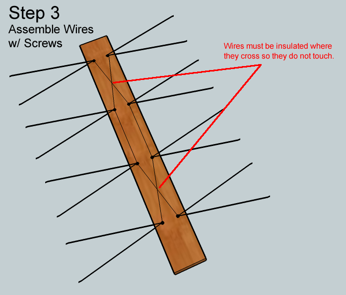
Is there any way to rectify this? I've checked on line and have seen some examples of building an indoor UHF antenna out of 8 V-shaped coat hanger sections (see image below), which is nothing like what I'm dealing with, but the one feature they do have is a pair of connecting rods that crisscross, each of which shares a fastener with 4 the V-shaped components. From what I've read, this configuration is important, so I'm wondering how I'd apply that to what I'm working with.
Or should I just forget about it and buy something?
| ||
|
|
Post# 923678 , Reply# 2 2/24/2017 at 23:47 (2,617 days old) by rp2813 (Sannazay) |
||
|
Thanks Paulo,
I guess the "active elements" of my antenna went to the scrap heap. I might be able to recreate one "half-wave dipole" pair at the rear of the section I have left.
All this time I thought the short "director" elements at the front end were for UHF, so that's why I saved that portion. Now I'm understanding that it's the wide-span dipoles that pull in the signals, whether VHF or UHF.
Since digital signals in my area are far more easily received than analog used to be, adding that one pair might be enough to improve reception over what I'm getting with the small indoor bow tie I'm currently using. It's worth a try.
| ||
|
Post# 923753 , Reply# 4 2/25/2017 at 12:31 (2,616 days old) by rp2813 (Sannazay) |
||
|
Eric, thanks for the suggestion but I'm looking for something much smaller. As stated above, the indoor bow tie is pulling in nearly every station available (the majority of transmitters are 45 miles away or less), but sometimes weather conditions cause pixelation, momentary loss of sound, or loss of signal altogether. All I need is a boost in reception that will eliminate these problems. | ||
|
Post# 923759 , Reply# 5 2/25/2017 at 13:16 (2,616 days old) by kb0nes (Burnsville, MN) |
||
Ralph, I'd love to see a photo of the cut end of your antenna. Combination VHF/UHF antennas have different active elements with a matching line connecting them together. Perhaps you still have the active UHF dipole in place that could be usable.
Next, have you ever done a TV Fool survey of your location? It would be good to confirm that you don't have any signals you want to receive in the High Band VHF frequencies, a UHF antenna isn't well suited for that. Here in the Minneapolis market we initially started out after the digital conversion all in the UHF range, but since about 4 stations have moved back into the VHF Ch 8-11 range. Link to the Signal Locater www.tvfool.com/index.phpQUESTIONM... Finally I built that 4-bay UHF antenna you showed. I always had an outdoor antenna back from the analog days. A couple years ago I had the exterior of the house redone so I pulled the antenna down. I wanted something to get me by as the work was done so I cobbled that antenna together. In my case with the VHF High stations I needed a bit better coverage below UHF so I added a 31" dipole element across the feed. This is effectively tuned at 181Mhz. I swept the completed antenna on my network analyzer and it looks good across the range I need to cover. The antenna is installed indoors and it does well for me, so well that I haven't re-installed an outdoor antenna. | ||
|
Post# 923817 , Reply# 6 2/25/2017 at 22:05 (2,616 days old) by rp2813 (Sannazay) |
||
|
Phil, I'll try to get a picture posted here tomorrow.
I've hatched a dipole plan that might improve things. Tomorrow may be a good day to try it, since it's supposed to be cloudy with possible showers, which presents perfect conditions to see if it will work. If not, then I may make myself one of those coat hanger rigs. | ||
|
Post# 923899 , Reply# 8 2/26/2017 at 11:38 (2,615 days old) by wayupnorth (On a lake between Bangor and Bar Harbor, Maine) |
||
 | ||
|
Post# 923941 , Reply# 9 2/26/2017 at 17:35 (2,615 days old) by rp2813 (Sannazay) |
||
|
Pictures Here's what I'm working with. The center section (the directors, I presume) looks to be slightly under 3' long.
The connecting block for the dipole is just inside the V-shaped reflector(s). From tip to tip it measures just under 12". Wing nuts are on the bottom. I had to JB Weld it because it had broken in half when the whole rig was tossed off the roof and onto the driveway. I don't know what the other orange piece with U-shaped rod was for. It's riveted so wasn't intended for any connective purpose. I removed the cut rods from the connector block since they no longer served a purpose. Most assuredly, they connected to a section of the longer elements behind what remains. I feel as though that missing connection to the rear section is what's diminishing this remnant's ability to pull in signals.
| ||
|
Post# 923985 , Reply# 12 2/26/2017 at 22:45 (2,615 days old) by kb0nes (Burnsville, MN) |
||
|
Opps apparently never hit post earlier...
Ralph, The two terminals you see on the dipole in your #3 photo are the connection point for the UHF corner reflector. You could just connect the two points to the leads of an outdoor Balun to adapt to your coax you are likely to run to the TV. Technically the standard Balun is also an impedance transformer which transforms a 300 ohm balanced connection (twinlead) to a 75 ohm unbalanced connection (coax). In this case your feed point of the corner reflector is actually close to 70 ohms so the 300-75 ohm transformer isn't needed. But 75 to 75 ohm Baluns aren't common. It would likely work fine anyhow even with the mismatch. The U shaped rod is a hairpin which is likely used for impedance matching and it also creates a DC short across the antenna feed to protect against static and voltages being built up across the feedline. It was part of the transmission line that linked the VHF section to the UHF. If you like to tinker and play by all means hook up the antenna and see how it goes. If you want an antenna that works with less fuss I'd buy a new one. The corrosion and lack of a proper matching section are likely to make this antenna not work like a new one. At least the digital signals are generally easier to receive a Q-5 picture with compared to the old VHF analog signals that had to deal with noise issues. | ||
|
Post# 923992 , Reply# 13 2/27/2017 at 00:15 (2,614 days old) by rp2813 (Sannazay) |
||
|
Thanks for the excellent explanations on what I'm dealing with. If I'm understanding things correctly, just that little dipole is pulling in the signal and the rest of the assembly is only there to help zero in on it. That's kind of amazing.
I gave the antenna a trial run, and reception was excellent on what had been weak and problematic channels, but the NBC affiliate rendered a "no signal" display. I tried aiming the antenna about 30 degrees in either direction from what I know was best when this rig was intact. Still "no signal." This is a deal-breaker, since I'd rather get NBC than more Asian language dramas and game shows.
I never would have believed that a little bow tie could pull signals indoors better than a rooftop unit.
Phil, I may take a shot at one of those 4-bay antennas. That may be all I need.
| ||
|
Post# 924004 , Reply# 14 2/27/2017 at 05:58 (2,614 days old) by kb0nes (Burnsville, MN) |
||
|
Ralph, are you positive that the NBC affiliate station isn't a VHF station? If you antenna works great on the others but not on this station it is a possibility. Since the digital change over, the number of the channel has zero relation to the frequency they choose to use. The "virtual" channels are confusing at times!
I'm 23 miles line of site to my transmitter complex here in MN. The 4 bay antenna worked great except for the 3 VHF High stations. If you have VHF stations the 4-bay may not do it for you. One other thing, if you build the antenna, avoid using coat hangers , steel just isn't that great a conductor for RF. It will work but why build with inferior materials? I used copper clad welding rod but solid copper house wiring would work well too, although it is hard to make it straight and pretty. | ||
|
Post# 924047 , Reply# 15 2/27/2017 at 13:16 (2,614 days old) by rp2813 (Sannazay) |
||
|
Phil, I've been wondering about whether the NBC channel could be VHF. In the analog days it was channel 11 but these days I don't know what it really is. It has always been an issue to receive 11's signal because the transmitter was south of town instead of north like all the other local stations. When it became the NBC affiliate, in order to serve the entire greater Bay Area, they moved their transmitter and changed media markets from Monterey to San Francisco, but they didn't move to where the bulk of local stations transmit from. Still, it's in the general area and shouldn't require a different aim than for the other channels. I'm pretty sure their tower is on the same hill as channel 2, which comes through fine most of the time.
Do you think I could use some 12 gauge romex wire for the 4-bay antenna? I've also contemplated harvesting dipoles from a set of rabbit ears and attaching them to the hairpin block by drilling holes for a couple of screws, and then connecting the rabbit ear dipole to the UHF dipole with some wire. I know spacing is key, so am not sure if fastening the rabbit ear dipole on the hairpin block would be the proper placement.
Last night, with mostly cloudy skies, I tweaked the bow tie arrangement I have the TV hooked up to, and all stations I care about came through. It's unsightly, but I might not be able to do much better. See attached picture, and yes, looping the twin lead around that one side of the bow tie makes a huge difference. The TV is a 19" Magnavox with built-in DVD and VHS players. It still delivers a sharp, crisp picture with perfect color.
View Full Size
| ||
|
Post# 924065 , Reply# 16 2/27/2017 at 15:21 (2,614 days old) by kb0nes (Burnsville, MN) |
||
|
Ralph, I just ran a TVfool channel listing for San Francisco. I used the zip code 94080. I'd really recommend running one for your exact address (or at least your Zipcode) so you really have an idea of what is where for you. I attached an image of the report. I assume you are talking about KNTV 11.1 which is on real channel 12 which would be about 205Mhz in the High VHF range. The San Fran area has more VHF channels then here in MN, typical of a denser population. I'd sure be designing in some VHF capability.
Using the wire from Romex would be fine or solid THHN single strand would work too. One thing that helps when using solid copper is to loop the ends around something like a broom stick and attach it to something solid and yank on it good. It helps straighten and work harden the wire so it holds shape better. UHF signals are prone to some absorption from moisture in the air, if it is foggy or humid or raining there may well be some degradation. If you are using the antenna indoors beware of what is in your walls. Stucco is often placed on a metal lath and it has high attenuation. Some asphalt shingles have conductive particles in them and that can cause a lot of loss, especially when wet. My house was aluminum siding and now that I have fiber cement the signal levels to my indoor antenna improved :) The other issue with UHF is that the peaks and nulls are much closer together. Moving the antenna just a foot or two could make all the difference in receiving a given station.
View Full Size
| ||
|
Post# 924126 , Reply# 17 2/28/2017 at 00:21 (2,613 days old) by rp2813 (Sannazay) |
||
|
Thanks Phil. I did learn that KNTV uses a VHF frequency. I think my rabbit ear dipole plan is worth a try.
Also, back when KNTV first began broadcasting in the '50s, because their transmitter was in the opposite direction from where area antennas were aimed, they distributed free small rooftop dipoles that could be spliced into the existing antenna system and aimed toward their transmitter. I still have one, so the other option is to hook it onto the UHF antenna's terminals with some twin lead. That would eliminate the need to create a fastening system for the rabbit ear dipoles.
I'll post a picture of the antenna tomorrow for your review. | ||
|
Post# 924181 , Reply# 18 2/28/2017 at 13:37 (2,613 days old) by rp2813 (Sannazay) |
||
|
Here's the KNTV antenna. If it helps with reception on that station, it will once again serve its original purpose some 60 years after it was issued. Due to one terminal screw having snapped off many years ago, the connection block can't be used as a splitter anymore, but the pair of terminals marked "SET" is all I need.
It's bordering on a Rube Goldberg solution, but if it works, that's all I care about. I'll test today and report back with results. | ||
|
Post# 924200 , Reply# 19 2/28/2017 at 15:47 (2,613 days old) by rp2813 (Sannazay) |
||
|
Results First I tried using just the KNTV antenna. Not all stations could be received, so I hooked up the UHF antenna as well. Now I receive every station without interference except KGO 7, which is still VHF. No matter how I aim the KNTV portion of this arrangement, there's an occasional blip in sound or momentary pixelation on KGO. Considering the fact that it's clear and sunny today, I expect issues with KGO on rainy or otherwise overcast days, which include summer when fog can often shroud the transmitter tower in SF where most stations' signals originate, even though it's sunny in the rest of the greater Bay Area.
Over all, it's an improvement over the set-top antenna. KGO 7 doesn't come in that much better, but other stations that would invariably have issues are now steady.
I don't know if constructing my own 4-bay antenna would improve things any further. Besides, right now I have the KNTV antenna aimed slightly differently from the UHF, and this wouldn't be possible with the 4-bay arrangement.
I'm not making any of this permanent until I've tested reception under various weather conditions. The ability to remove the unsightly set-top rigging would be a plus if all goes well. | ||
|
Post# 924244 , Reply# 20 2/28/2017 at 21:03 (2,613 days old) by kb0nes (Burnsville, MN) |
||
|
Neat antenna that the station provided, cool piece of history too.
It appears that the folded dipole section is about 22" long which works out to being resonant at about 207 Mhz. The rod parallel to the dipole is parasitic reflector to give the antenna a few db of directivity with the front being the dipole. Remember that all this is 300ohm so you could connect a 300-75 ohm balun at across that dipole to run coax to the set. It is a pity that your UHF corner reflector doesn't also have a folded dipole so that it's feed point would also be 300 ohms. You could actually form a folded dipole for that corner reflector to replace the stock open dipole. Here is a handy webpage with a folded dipole dimension calculator if you want to experiment. www.changpuak.ch/electronics/Dipo...
View Full Size
| ||
|
Post# 924245 , Reply# 21 2/28/2017 at 21:34 (2,613 days old) by rp2813 (Sannazay) |
||
|
Thanks Phil -- your information above reveals that I have the KNTV antenna aimed backwards. I'll turn it around and see what happens. Just for the record, KGO has been on for the past three hours and there hasn't been a single issue. I would think that turning the KNTV antenna around could only improve on the progress I've made.
I'll look into making a folded dipole for the UHF remnant. I'm not sure where I'd find aluminum tubing, or whether using a tube bender would work to "fold" one. | ||
|
Post# 924437 , Reply# 22 3/1/2017 at 23:58 (2,612 days old) by rp2813 (Sannazay) |
||
|
I turned the KNTV antenna around so everything is now properly aimed. I'm receiving all available channels with absolutely ZERO interference! It seems odd not to be dealing with hiccups and temporary loss of sound.
A scan performed by the digital tuner box picked up one additional channel that broadcasts on VHF from about 20 miles south of here, so am assuming the VHF antenna gets credit for that one. It offers nine appearances, each of which are religious in nature, so I manually deleted all of them. This is why my excursions to Reno are few and far between.
The real test comes this weekend when some rain is expected. I don't think I can do any better with what I have, so if the rain and/or related cloud deck cause trouble, that will suggest the need to upgrade. | ||
|
Post# 924518 , Reply# 23 3/2/2017 at 14:46 (2,611 days old) by sudsmaster (SF Bay Area, California) |
||

A while back Costco had some digital TV antennas on sale. They have a grid not unlike the Channel Master 4221 pictured above, but probably a lot smaller.
I have one mounted on one chimney here, and it's mixed in with a standard UHF/VHF christmas tree style antenna on the other chimney. They are joined with a coax switch box. I usually don't see much difference if one, or the other, or both are mixed in. There's also a signal booster after the switch box because I run coax from the antennae to every room in the house. The digital reception here is generally great - high def on nearly all channels. Some times I rotate the old antenna this way or that to try to capture North Bay signals, but in general that is not successful. Occasionally the TV tuner scanner will pick up analog/digital signals around Channel 1, but these are generally without content. I wonder if it's from a nearby hospital or something. It would probably be fun to put a rotation motor on the older tree antenna, to see just what I can pick up with it. When I get a Round-To-It... | ||
|
Post# 924524 , Reply# 24 3/2/2017 at 15:10 (2,611 days old) by rp2813 (Sannazay) |
||
|
Rich, I checked around on line for a list of OTA channels to see if I was pulling in everything within reason, and found the rundown in the link provided. It appears north bay channels primarily offer duplicate programming of what's provided on stations in closer proximity that I can easily receive.
The only station I'd like to receive but has its transmitter to the south of here is KSBW 8 out of Salinas/Monterey. They cover the Santa Cruz weather forecast in more detail than SF Bay Area stations do, and have a no-nonsense/no hype meteorologist who is also a licensed pilot and puts a practical spin on things. CLICK HERE TO GO TO rp2813's LINK | ||
|
Post# 924551 , Reply# 25 3/2/2017 at 20:01 (2,611 days old) by sudsmaster (SF Bay Area, California) |
||
|
Most of the stations I receive appear to be broadcast from Sutro Tower in SF, or from Mt. San Bruno just to the south of there. I also can get KCSM which is the College of San Mateo. KNTV I think has a repeater up in the SF area - they probably had to do that after they took over the NBC license (KRON was forced out of NBC because of its ownership of the SF Chronicle). Apparently there's a law that TV stations cannot own newspapers in the same local market, and vice verse.
Also since digital signals don't travel as far as VHF analog, if KNTV had kept on broadcasting from San Jose only, then it might have lost as lot of market to the north. I would like to get some North Bay stations, particularly the public TV station that shows regular NHK programming, such as "Begin Japanology", which despite the slightly strange name, is a gem of a 30 minute documentary series about various aspects of Japanese life, culture, and products. It can be viewed on the Internet but it's just not the same as setting the recorder and watching it later. It used to be broadcast on one of the SF digital stations, but was dropped a few years back. Now the nearest broadcast station is somewhere in Sonoma County, and can't get that here, at least not over the air digitally. CLICK HERE TO GO TO sudsmaster's LINK | ||
|
Post# 924642 , Reply# 26 3/3/2017 at 11:45 (2,610 days old) by kb0nes (Burnsville, MN) |
||
|
digital signals don't travel as far as VHF analog
This mostly seems true since the majority of digital signals are frequently UHF, the transmission mode doesn't change propagation. VHF signals penetrate structures and foliage better and suffer less absorption from moisture (but they do suffer more from noise). This is the reason that many of the broadcasters dropped back into their high band VHF channel allocations shortly after the digital migration. Our market here in MN went all UHF initially but when allowed a handful of stations have dropped back into the channel 8-11 range. They seldom seem to use the low VHF range mostly due to antenna size and the possibility of non-line of sight propagation interference (skip).
As for digital vs analog on the same frequency the coverage area for a perfect picture with digital is larger as a generalization. Digital signals deal with noise and multipath far better and have a narrower bandwidth. The bad thing is with digital transmission is when you start to get on the edge, then only a minor fluctuation will cause artifacts or total lost of picture. It would be really interested to have an antenna on a rotator just to experiment. If I were to do that I'd be sure to get pretty good sized antenna and pay attention to the front to back ratio. Not a lot of sense in messing with a rotor unless the antenna is pretty pointy. I have one friend here that has a tower with a rotatable stacked pair of FM antennas on it. Each antenna has an 18 foot boom and they are phased together with a mast mounted preamp. A tunable pre-selector helps kill the strong first ajacents. He can receive FM in stereo from ~200 miles on most days and with a tropospheric enhancement occasionally signals from 1000 miles distant will come up! | ||
|
Post# 924680 , Reply# 27 3/3/2017 at 15:08 (2,610 days old) by rp2813 (Sannazay) |
||
|
Phil, I think your post directly above explains why KGO has been more problematic than other stations.
Today we have some high clouds in advance of a weak weather system due in here tomorrow, and KGO is displaying slight, infrequent choppiness, mainly momentary loss of sound. It's not horrible, but per the link I posted further up, KGO broadcasts on low band VHF from the tower in SF, and on UHF from a transmitter closer to me, but the nearby tower is NE of here instead of NW, which is the direction I have the UHF antenna aimed.
Apparently KGO's VHF signal is too weak from the SF location so I think what I'm getting is coming from the nearby UHF tower. I've aimed the VHF antenna to the NE, but realize it's not designed to receive UHF, and am not seeing much improvement. I think KGO will remain an issue except in fair weather, at least until I make a decision on upgrading. Maybe I need to revisit the rabbit ear dipole addition on the UHF antenna's hairpin block, or just upgrade to a modern rig that will receive both VHF and UHF.
The reason I think I'm receiving the KGO signal over UHF is because when I ran a new channel scan on the converter box, I ended up with duplicates of channel 2, which has a similar arrangement over separate transmitters in the same locations as KGO, but channel 2 broadcasts over UHF from both. So far, appearances of channel 2 from both towers are coming across fine. | ||
|
Post# 925016 , Reply# 28 3/5/2017 at 05:03 (2,608 days old) by sudsmaster (SF Bay Area, California) |
||
|
Last month KPIX was experiencing a lot of dropouts and coarse pixelation. Not sure if it was weather related or a station broadcasting issue. This month it appears better. Don't generally have a problem with KGO, but then I'm a lot closer to Mt. Sutro than you are.
I remember when KGO was the only station transmitting from Mt. Sutro. We used to live nearby the Mt. and my brother and I used to take walks up there. I remember when the big tower went on top, it's probably about as tall as the Eiffel Tower, except on top of a mountain, and nowhere near as charming. Think War of the Worlds Martian mechanical destruction device in bright orange. It was promised to give a ghost free picture in every corner of the city, but oddly those right under it got worse reception. | ||
|
Post# 925109 , Reply# 29 3/5/2017 at 12:39 (2,608 days old) by rp2813 (Sannazay) |
||
|
It seems strange when a little college station like KCSM/60 with presumably weaker signal can be received more reliably than a network affiliate like KGO/7, even though they're both broadcasting from the same tower. I've decided I can't improve reception on KGO with my current system, but it's not bad enough to make me go out and buy a new antenna. We'll see what happens when SF's summer fog season kicks in.
Also, I just heard that negotiations are in progress to sell KCSM, so we can say goodbye to the only PBS alternative to the bloated KQED empire in this market. Prepare for foreign language, shopping, infomercial or religious broadcasts on channel 60 down the road. | ||
|
Post# 925110 , Reply# 30 3/5/2017 at 12:50 (2,608 days old) by ea56 (Cotati, Calif.) |
||
Ralph,
I don't know a whole lot about tv antenna's other than we used to use them before cable tv. But as a life long resident of the greater Bay Area I can safely state that KGO always had the weakest signal, no matter where we lived, even when we were just across the Bay in El Cerrito. There was always more interference on channel 7. Sometime's I even remember that when we were using rabbit ears one of us would have to hold one of the rabbit ears to get 7 to come in clear. Yet we could get KCRA from Sacramento clear as a bell and it was about 80 or more miles away. Seems like an ABC affiliate would have had a more powerful transmitter.
Eddie | ||
|
Post# 925114 , Reply# 31 3/5/2017 at 13:11 (2,608 days old) by sudsmaster (SF Bay Area, California) |
||
|
Sale of KCSM?
Ralph,
That's bad news. I enjoy the jazz (music only) station 60.3, as well as the France24 (Fraaaance-van-cat) continuous coverage. Oh, well, there's always internet streaming... France 24 Live Stream | ||
|
Post# 925135 , Reply# 32 3/5/2017 at 15:01 (2,608 days old) by rp2813 (Sannazay) |
||
|
Eddie, thanks for confirming that KGO has always been quirky. I sort of recall it being ghosty in the olden days when other network affiliates were fine, even though most were broadcasting from the same general area before Sutro tower went up. The other station that tended to come through less than perfectly was KTVU channel 2. I remember on our 1951 Capehart, 2 was always a bit snowy. It improved when we got our '62 Airline, but with rabbit ears on other sets, 2 was more compromised, and 7 (KGO) always needed adjustments.
I read many, many years ago that the reason so many ABC stations are found on channel 7 is because there was a rumor or concern in the early days of TV (cold war era?) that the FCC or whatever agency might claim the use of the lower VHF frequencies for government use, so by snapping up all of the channel 7 frequencies, ABC would essentially be the first viewable channel on the dial. In the days before remote control, that was a strategic position. I don't know if there's any truth to this legend, since ABC was late to the TV party behind NBC and CBS anyway. In the end, ABC landed downstream from NBC and CBS, which in major markets can usually be found somewhere in the range of channels 2 through 5.
Rich, it gets worse re: Channel 60. In that same story I mentioned above, it was reported that the jazz station KCSM (91.1 FM or 60.3 on TV) has cut staff and live programming and is now running some shows prerecorded out of Chicago. A source at KCSM didn't exactly confirm or deny rumors that the radio station is up for sale (presumably ours is a hot market for radio and there's no shortage of potential buyers), so we might be saying goodbye to jazz in the Bay Area for good this time, as there probably isn't anyone willing to step in like KCSM did to fill the void left when KJAZ was sold quite a few years ago. | ||
|
Post# 925166 , Reply# 33 3/5/2017 at 17:06 (2,608 days old) by sudsmaster (SF Bay Area, California) |
||
|
Ralph,
Thanks to corporate chain ClearChannel, local radio has become a wasteland of sorts. Gone: KKSF, which played great "smooth jazz" for a few decades, and had an equally great annual "Sampler for Aids Relief" CD release with the best smooth jazz hits of the year. Gone: KDFC, the area's sole remaining classical music station, albeit it returned last year as a low power public station, with limited reception and the usual interminable pledge breaks. For a while digital HD radio seemed to be picking up some pieces, such a digital branch of KISS-FM picking up the smooth jazz format. Sadly, they dropped that format in favor of mass produced hip hop dreck last year, so even that work around for the dearly departed KKSF has gone under. At work I find I'm listening mostly to live streaming of KDFC on my Bluetooth headphones. It works well enough since the desktop system has a powerful enough bluetooth capability, except for the aforementioned pledge breaks. It is perhaps the direction that a lot of quality radio is going - dropping broadcast or having limited, low power broadcast capability, in favor of internet audio streaming. | ||
| Forum Index: | 
| Other Forums: |

|

|

|

|

|

 Comes to the Rescue!


;)
;)
;)
;)
;)
;)